Page 226 - Subyek Computer Aided Design - [David Planchard] Engineering Design with SOLIDWORKS
P. 226

Fundamentals of Assembly Modeling                                                                                                                          Engineering Design with SOLIDWORKS® 2018


                                                The assembled relationship between the ROD and the GUIDE is called the fit. The fit is


                                                defined as the tightness or looseness between two components. This project discusses


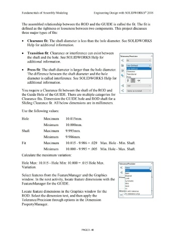
                                                three major types of fits:


                                                •  Clearance fit:  The shaft diameter is less than the hole diameter. See SOLIDWORKS


                                                            Help for additional information.


                                                •  Transition fit:  Clearance or interference can exist between


                                                            the shaft and the hole. See SOLIDWORKS Help for                                                                                                                                                        Tolerance/ Precision
                                                                                                                                                                                                                                                                       ... ,  I


                                                                                                                                                                                                                                                                       5
                                                            additional information.                                                                                                                                                                                  1. o         Fit
                                                                                                                                                                                                                                                                       -.01


                                                •           Press fit: The shaft diameter is larger than the hole diameter .                                                                                                                                                     Clearance


                                                            The difference between the shaft diameter and the hole                                                                                                                                                               Transitional


                                                                                                                                                                                                                                                                                  Press
                                                            diameter is called interference. See SOLIDWORKS Help for

                                                                                                                                                                                                                                                                                 .l!l        HJ         HJl.6
                                                                                                                                                                                                                                                                                  g6         g6           1'
                                                            additional information.


                                                                                                                                                                                                                                                                        .0 1
                                                                                                                                                                                                                                                                      X.~~;       .123                                            v


                                                                                                                                                                                                                                                                       +.xx
                                                You require a Clearance fit between the shaft of the ROD and                                                                                                                                                         1.50          Same as nominal                                v
                                                                                                                                                                                                                                                                       -.x,c


                                                the Guide Hole of the GUIDE. There are multiple categories for


                                                Clearance fits. Dimension the GUIDE hole and ROD shaft for a


                                                Sliding Clearance fit.  All below dimensions are in millimeters.


                                                Use the following values:


                                                Hole                                           Maximum                                         10.015mm.


                                                                                               Minimum                                         10.000mm.


                                                Shaft                                          Maximum                                        9.995mm.


                                                                                               Minimum                                        9.986mm.


                                                Fit                                            Maximum                                         10.015 - 9.986 =  .029  Max. Hole - Min. Shaft.


                                                                                               Minimum                                         10.000 - 9 .995 =  .005  Min. Hole - Max. Shaft.


                                                Calculate the maximum variation:


                                                Hole Max: 10.015 - Hole Min:  10.000 =  .015 Hole Max.                                                                                                                                                           Tolerance/ Precision


                                                Variation.                                                                                                                                                                                                         ,.so        None
                                                                                                                                                                                                                                                                    +,0 1
                                                                                                                                                                                                                                                                    -.o,


                                                                                                                                                                                                                                                                     . 01
                                                                                                                                                                                                                                                                   x.xxx      B  .
                                                                                                                                                                                                                                                                     · 01       as1c
                                                Select features from the FeatureManager and the Graphics                                                                                                                                                                      Bilateral

                                                                                                                                                                                                                                                                 Primar L'  .t
                                                                                                                                                                                                                                                                                1m1
                                                window. In the next activity, locate feature dimensions with the

                                                                                                                                                                                                                                                                              Symmetric

                                                FeatureManager for the GUIDE.                                                                                                                                                                                                 MIN


                                                                                                                                                                                                                                                                              MAX

                                                                                                                                                                                                                                                                              Fit

                                                Locate feature dimensions in the Graphics window for the                                                                                                                                                         Dimen Fit with tolerance


                                                                                                                                                                                                                                                                I (xx) I~ Fit (tolerance only)
                                                ROD. Select the dimension text, and then apply the


                                                Tolerance/Precision through options in the Dimension


                                                Property Manager.


                                                                                                                                                                                PAGE 3-48
   221   222   223   224   225   226   227   228   229   230   231