Page 228 - Subyek Computer Aided Design - [David Planchard] Engineering Design with SOLIDWORKS
P. 228

Fundamentals of Assembly Modeling                                                                                                                          Engineering Design with SOLIDWORKS® 2018


                                                   , 1 /


                                                  -;Q~ ISO symbol Hole/Shaft Classification is applied to an


                                                                                                                                                                                                                                                                   Tolerance/Precision
                                                individual dimension for Fit, Fit with tolerance, or Fit (tolerance                                                                                                                                                       1

                                                                                                                                                                                                                                                                     ,.;0°      rFit                                              v
                                                                                                                                                                                                                                                                       - . 0 1
                                                only) types. Classification can be User Defined, Clearance,


                                                Transitional or Press.


                                                                                                                                                                                                                                                                                 Clearance


                                                For a hole or shaft dimension, select a classification from the                                                                                                                                                                  Transitional

                                                                                                                                                                                                                                                                                 Press
                                                list. The Hole/Shaft designation for a Sliding Fit is H7 /g6.                                                                                                                                                                    .fil.


                                                                                                                                                                                                                                                                                  96         HJ         H7'-6
                                                                                                                                                                                                                                                                                             96
                                                                                                                                                                                                                                                                                                          1~
                                                                                                                                                                                                                                                                        .01  I                                                    v
                                                                                                                                                                                                                                                                                 .123
                                                                                                                                                                                                                                                                     x.xxx
                                                The values for Maximum and Minimum tolerances are                                                                                                                                                                       .01     ~------

                                                                                                                                                                                                                                                                       +.xx  I
                                                calculated automatically based on the diameter of the Hole/Shaft                                                                                                                                                     ,.~~.         Same as nominal                                v


                                                and the Fit Classification.


                                                   , 1 /


                                                  -;Q~ Utilize Hole/Shaft Classification early in the design


                                                process. If the dimension changes, then the tolerance updates.


                                                The Hole/Shaft Classification propagates to the details in the


                                                drawing. Create the drawing in Project 4. See SOLIDWORKS


                                                Help for additional information.


                                                                                                                                                                                                                                                                                                                                     >

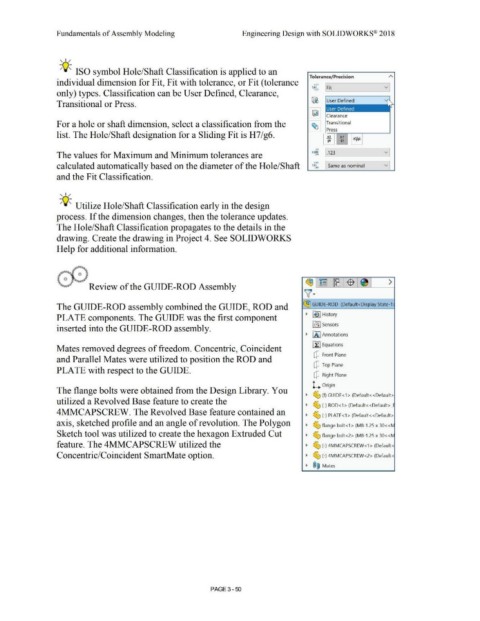
                                                                           Review of the GUIDE-ROD Assembly


                                                The GUIDE-ROD assembly combined the GUIDE, ROD and                                                                                                                                                            ~ GUIDE-ROD  (Default<Display State-1.


                                                PLATE components. The GUIDE was the first component                                                                                                                                                             •  ~ I History


                                                                                                                                                                                                                                                                     ifiJ Sensors
                                                inserted into the GUIDE-ROD assembly.


                                                                                                                                                                                                                                                                • fA I Annotations


                                                                                                                                                                                                                                                                     ~ Equations
                                                Mates removed degrees of freedom. Concentric, Coincident


                                                                                                                                                                                                                                                                       [?  Front Plane
                                                and Parallel Mates were utilized to position the ROD and

                                                                                                                                                                                                                                                                       [?  Top Plane
                                                PLATE with respect to the GUIDE.

                                                                                                                                                                                                                                                                       [?  Right Plane


                                                                                                                                                                                                                                                                      L  Origin
                                                The flange bolts were obtained from the Design Library. You

                                                                                                                                                                                                                                                                •  ~ (f) GUIDE<1 > (Default<<Default>
                                                utilized a Revolved Base feature to create the

                                                                                                                                                                                                                                                                •  ~ (-) ROD<1> (Default<<Default>_I

                                                4MMCAPSCREW. The Revolved Base feature contained an
                                                                                                                                                                                                                                                                •  ~ (-) PLATE<1 > (Default< <Default>


                                                axis, sketched profile and an angle of revolution. The Polygon                                                                                                                                                  •  ~ flange bolt<1> (M8-1.25 x 30<<N


                                                Sketch tool was utilized to create the hexagon Extruded Cut                                                                                                                                                     •  ~ flange bolt<2> (M8-1.25 x 30<<N


                                                feature. The 4MMCAPSCREW utilized the                                                                                                                                                                           •  ~ (-) 4MMCAPSCREW<1>  (Default<


                                                Concentric/Coincident SmartMate option.                                                                                                                                                                         •  ~ (-) 4MMCAPSCREW<2> (Default<


                                                                                                                                                                                                                                                                •  ®@  Mates


                                                                                                                                                                                PAGE 3 - 50
   223   224   225   226   227   228   229   230   231   232   233