
Page 197 - Subyek Computer Aided Design - [David Planchard] Engineering Design with SOLIDWORKS
P. 197
Engineering Design with SOLIDWORKS® 2018 Fundamentals of Assembly Modeling
Utilize the Quick Mate procedure for Standard mates, Cam mate, Profile Center mate,
Slot mate, Symmetric mate and Width mate. To activate the Quick Mate functionality,
click Tools, Customize. On the toolbars tab, under Context toolbar settings, select Show
Quick Mates. Quick Mate is selected by default.
GUIDE-ROD Assembly - Mate the ROD Component
Recall the initial assembly design constraints:
• The ROD requires the ability to travel through the GUIDE.
• The face of the Keyway in the ROD is parallel to the right face of the GUIDE.
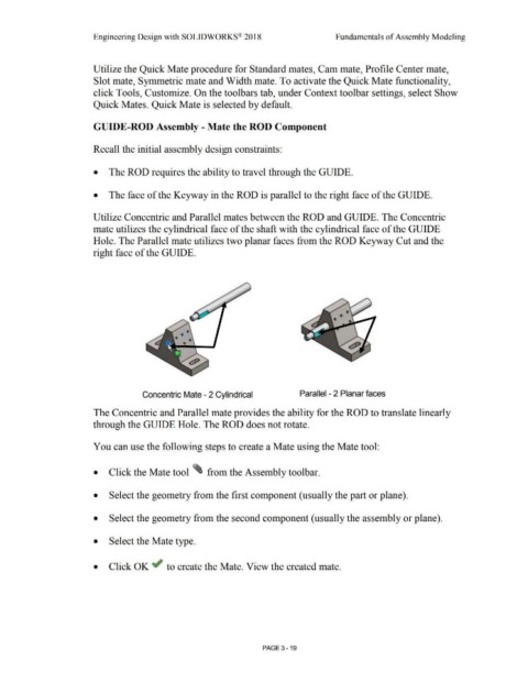
Utilize Concentric and Parallel mates between the ROD and GUIDE. The Concentric
mate utilizes the cylindrical face of the shaft with the cylindrical face of the GUIDE
Hole. The Parallel mate utilizes two planar faces from the ROD Keyway Cut and the
right face of the GUIDE.
Concentric Mate - 2 Cylindrical Parallel - 2 Planar faces
The Concentric and Parallel mate provides the ability for the ROD to translate linearly
through the GUIDE Hole. The ROD does not rotate.
You can use the following steps to create a Mate using the Mate tool:
• Click the Mate tool ~ from the Assembly toolbar .
• Select the geometry from the first component (usually the part or plane) .
• Select the geometry from the second component (usually the assembly or plane) .
• Select the Mate type .
• Click OK if to create the Mate. View the created mate .
PAGE 3- 19