
Page 186 - Subyek Computer Aided Design - [David Planchard] Engineering Design with SOLIDWORKS
P. 186
Fundamentals of Assembly Modeling Engineering Design with SOLIDWORKS® 2018
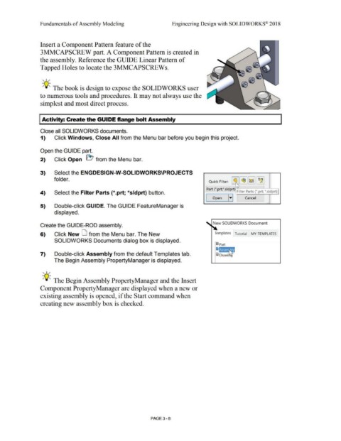
Insert a Component Pattern feature of the
3MMCAPSCREW part. A Component Pattern is created in
the assembly. Reference the GUIDE Linear Pattern of
Tapped Holes to locate the 3MMCAPSCREWs.
' '"
-;Q~ The book is design to expose the SOLIDWORKS user
to numerous tools and procedures. It may not always use the
simplest and most direct process.
I Activity: Create the GUIDE flange bolt Assembly
Close all SOLIDWORKS documents.
1) Click Windows, Close All from the Menu bar before you begin this project.
Open the GUIDE part.
2) Click Open ~ from the Menu bar.
3) Select the ENGDESIGN-W-SOLIDWORKS\PROJECTS
folder. Quick Filter: ~~ I ~II~ 11 f~ I
.----1 ';,,.----,
' Part (*.prt;*.sldprt) ;ilter Parts (*.prt/ *.sldprt)
4) Select the Filter Parts {*.prt; *sldprt) button.
I Open ITI Cancel
•
5) Double-click GUIDE. The GUIDE FeatureManager is
displayed.
New SOLIDWORKS Document
Create the GUIDE-ROD assembly.
6) Click New LJ from the Menu bar. The New Templates Tutorial MY-TEMPLATES
SOLIDWORKS Documents dialog box is displayed.
7) Double-click Assembly from the default Templates tab.
The Begin Assembly PropertyManager is displayed.
' '"
-;Q~ The Begin Assembly PropertyManager and the Insert
Component PropertyManager are displayed when a new or
existing assembly is opened, if the Start command when
creating new assembly box is checked.
PAGE 3- 8