
Page 183 - Subyek Computer Aided Design - [David Planchard] Engineering Design with SOLIDWORKS
P. 183
Engineering Design with SOLIDWORKS® 2018 Fundamentals of Assembly Modeling
An assembly combines two or more parts. In an assembly, parts are referred to as
components. Design constraints directly influence the assembly design process. Other
considerations indirectly affect the assembly design, namely cost, manufacturability and
serviceability.
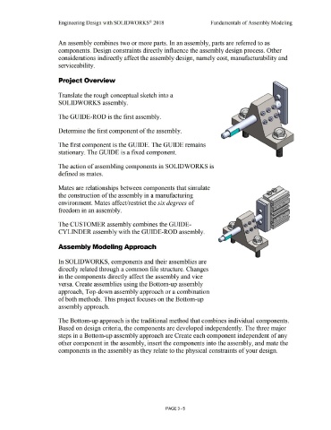
Project Overview
Translate the rough conceptual sketch into a
SOLIDWORKS assembly.
The GUIDE-ROD is the first assembly.
Determine the first component of the assembly.
The first component is the GUIDE. The GUIDE remains
stationary. The GUIDE is a fixed component.
The action of assembling components in SOLIDWORKS is
defined as mates.
Mates are relationships between components that simulate
the construction of the assembly in a manufacturing
environment. Mates affect/restrict the six degrees of
freedom in an assembly.
The CUSTOMER assembly combines the GUIDE-
CYLINDER assembly with the GUIDE-ROD assembly.
Assembly Modeling Approach
In SOLIDWORKS, components and their assemblies are
directly related through a common file structure. Changes
in the components directly affect the assembly and vice
versa. Create assemblies using the Bottom-up assembly
approach, Top-down assembly approach or a combination
of both methods. This project focuses on the Bottom-up
assembly approach.
The Bottom-up approach is the traditional method that combines individual components.
Based on design criteria, the components are developed independently. The three major
steps in a Bottom-up assembly approach are Create each component independent of any
other component in the assembly, insert the components into the assembly, and mate the
components in the assembly as they relate to the physical constraints of your design.
PAGE3 - 5