
Page 184 - Subyek Computer Aided Design - [David Planchard] Engineering Design with SOLIDWORKS
P. 184
Fundamentals of Assembly Modeling Engineering Design with SOLIDWORKS® 2018
In the Top-down assembly approach, major
l:rn fo ~ I
design requirements are translated into \7-
assemblies, sub-assemblies and components. L, Origin
• IC@ (f) Side< 1 > (Standard < <Standard> _I
• ~ Side<2> (Standard< <Standard> _Dis
, 1 / • ~ Ball<1 > (Standard<<Standard> _Pho
• ~ Handle<1> (Standard<<Standard>_I
-;Q~ In the Top-down approach, you do not (!, I Part1 lnplace Mate 11-1 ]<1> -> (
11
need all of the required component design • fil Mates in lnplace Mate 11-1
• ~] History
details. Individual relationships are required. ~ Sensors
• IA] Annotations
rfl Equations
.,_
Example: A computer. The inside of a ~~ Material <not specified>
C!J Front Plane
computer can be divided into individual key
C!J Top Plane
sub-assemblies such as a motherboard, disk drive, power [iJ Right Plane
L Origin
supply, etc. Relationships between these sub-assemblies • ~ Boss-Extrudel ->
must be maintained for proper fit. • ~ ( Part2"1nplace Mate 11-1 )<1> ·> (
Use the Bottom-up design approach for the GUIDE-ROD
assembly and the CUSTOMER assembly.
Linear Motion and Rotational Motion Mother Power
Board Supply
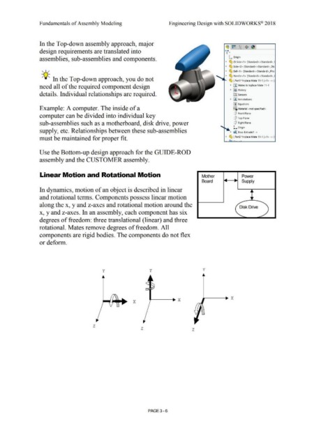
In dynamics, motion of an object is described in linear
and rotational terms. Components possess linear motion
along the x, y and z-axes and rotational motion around the Disk Drive
x, y and z-axes. In an assembly, each component has six
degrees of freedom: three translational (linear) and three
rotational. Mates remove degrees of freedom. All
components are rigid bodies. The components do not flex
or deform.
y y v
x
z
z z
PAGE 3- 6