
Page 187 - Subyek Computer Aided Design - [David Planchard] Engineering Design with SOLIDWORKS
P. 187
Engineering Design with SOLIDWORKS® 2018 Fundamentals of Assembly Modeling
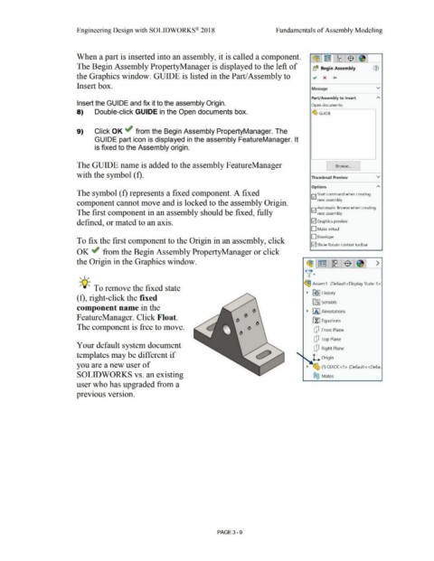
When a part is inserted into an assembly, it is called a component.
The Begin Assembly PropertyManager is displayed to the left of b($ Begin Assembly
the Graphics window. GUIDE is listed in the Part/Assembly to .,, x +
Insert box. Message v
Part/Assembly to Insert
Insert the GUIDE and fix it to the assembly Origin. Open documents:
8) Double-click GUIDE in the Open documents box. ~ GUIDE
9) Click OK ~ from the Begin Assembly PropertyManager. The
GUIDE part icon is displayed in the assembly FeatureManager. It
is fixed to the Assembly origin.
The GUIDE name is added to the assembly FeatureManager Browse ...
with the symbol (f). Thumbnail Preview v
Options
The symbol ( f) represents a fixed component. A fixed !vi Start command when creating
new assembly
component cannot move and is locked to the assembly Origin.
!vi Automatic Browse when creating
The first component in an assembly should be fixed, fully new assembly
defined, or mated to an axis. 52] Graphics preview
D Make virtual
D Envelope
To fix the first component to the Origin in an assembly, click
52] Show Rotate context toolbar
OK ~ from the Begin Assembly PropertyManager or click
the Origin in the Graphics window. ~,~ :~1$ 1 >
, ,/ v·
~ Assem1 (Default<Display State-1 >:
-;Q::. To remove the fixed state
~ [€> I History
(f), right-click the fixed
t0] Sensors
component name in the
~ [A I Annotations
FeatureManager. Click Float.
0 ~ Equations
The component is free to move.
dJ Front Plane
dJ Top Plane
Your default system document
[P Right Plane
templates may be different if
L Origin
you are a new user of ~ ~ (f) GUIDE<1 > (Default<<Defau
SOLIDWORKS vs. an existing ®@ Mates
user who has upgraded from a
• •
previous version.
PAGE 3 - 9