Page 182 - Subyek Computer Aided Design - [David Planchard] Engineering Design with SOLIDWORKS
P. 182

Fundamentals of Assembly Modeling                                                                                                                          Engineering Design with SOLIDWORKS® 2018


                                                Project Situation


                                                The PLATE, ROD and GUIDE parts were created in Project 2. Perform the following


                                                steps:


                                                Step 1: Insert the ROD, GUIDE and PLATE into a GUIDE-ROD assembly.


                                                Step 2: Obtain the customer's GUIDE-CYLINDER assembly using 3D ContentCentral.


                                                The assembly is obtained to guarantee proper fit between the GUIDE-ROD assembly and


                                                the customer's GUIDE-CYLINDER assembly.


                                                Step 3: Create the CUSTOMER assembly. The CUSTOMER assembly combines the


                                                GUIDE-ROD assembly with the GUIDE-CYLINDER assembly.


                                                Review the GUIDE-ROD assembly design constraints:


                                                •  The ROD requires the ability to travel through the GUIDE.


                                                •  The ROD keyway is parallel to the right surface of the GUIDE. The top surface of the


                                                            GUIDE is parallel to the work area.


                                                •  The ROD mounts to the PLATE. The GUIDE mounts to a flat work surface.


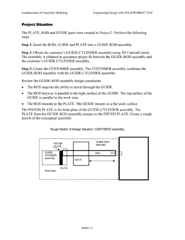
                                                The PISTON PLATE is the front plate of the GUIDE-CYLINDER assembly. The


                                                PLATE from the GUIDE-ROD assembly mounts to the PISTON PLATE. Create a rough


                                                sketch of the conceptual assembly.


                                                                                                             Rough Sketch of Design Situation: CUSTOMER assembly


                                                                                      --------------------------------


                                                                                                                                                                                                                 GUIDE-ROD
                                                                                                                     PISTON
                                                                                                                                                                                                                 assembly


                                                                                                                  ~E .....-----,
                                                                                                                                         ....... __ ...... ______ ...... __________ ...


                                                                                                   GUIDE-                                                                                                      ROD


                                                                                                   CYLINDER


                                                                                                  assembly
                                                                                                                                                                  GUIDE


                                                                                                                                    PLATE


                                                                                                  Work Area


                                                                                      ---------------------------------------------


                                                                                                                                                                                  PAGE 3-4
   177   178   179   180   181   182   183   184   185   186   187