
Page 158 - Subyek Computer Aided Design - [David Planchard] Engineering Design with SOLIDWORKS
P. 158
Funda1nentals of Part Modeling Engineering Design with SOLIDWORKS 2018
' I/
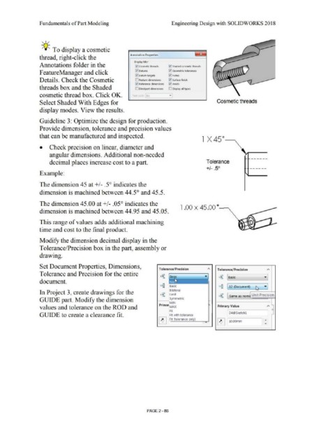
;Q;: To display a cosmetic
Annotation Properties
thread, right-click the
Display filter
Annotations folder in the 0 Cosmetic threads 10 Shaded cosmetic threads
F eatureManager and click l:{!Datums 10 Geometric tolerances
.t.l Datum targets 0 Notes
Details. Check the Cosmetic ;::] Feature dimensions 10 Surface finish
,/ Reference dimensions 0 welds
threads box and the Shaded [J DimXpert dimensions [) Display all types
cosmetic thread box. Click OK. Text cale 1:1
Select Shaded With Edges for Cosmetic threads
display modes. View the results.
Guideline 3: Optimize the design for production.
Provide dimension, tolerance and precision values
that can be manufactured and inspected.
1 x 45°--..
• Check precision on linear, diameter and
angular dimensions. Additional non-needed
decimal places increase cost to a part. Tolerance
+/- _50
Example:
The dimension 45 at +/- .5° indicates the
dimension is machined between 44.5° and 45.5.
The dimension 45.00 at +/- .05° indicates the
1 .00 X 45.00 °~
dimension is machined between 44.95 and 45.05.
This range of values adds additional machining
time and cost to the final product.
Modify the dimension decimal display in the
Tolerance/Precision box in the part, assembly or
drawing.
Set Document Properties, Dimensions, ,..
Tolerance/Precision Tolerance/Precision
Tolerance and Precision for the entire •.01 •,01
1.50
-.01 150 [ Basic ·I
... 01
document.
·"
•••
X.ICXX Basic X.XIX ·I
·" ••• [ .12 (Document) ~
In Project 3, create drawings for the .,. Bilateral
•,.X:C
1.SO Limit !SO Unit Precision
•.ICX -.xx Same as nomi
GUIDE part. Modify the dimension Symmetric
MIN ,.. -
values and tolerance on the ROD and Primar MAX Primary Value
Fit D4@Sketchl 0
GUIDE to create a clearance fit. Fit with tolerance
~ ....
~ Fit (tolerance only) ..
10.00mm
PAGE 2-86