
Page 153 - Subyek Computer Aided Design - [David Planchard] Engineering Design with SOLIDWORKS
P. 153
Engineering Design with SOLIDWORKS® 2018 Fundamentals of Part Modeling
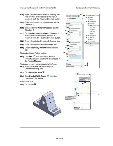
574) Enter 1 Omm in the Direction 1 Spacing box. •
'"' ~ GUIDE (Default< <Defa
The direction arrow points to the right. If
• R91 History
required, click the Reverse Direction button. gg Linear Pattern
l0:J Sensors
~ x
575) Enter 3 in the Number of Instances box for • iA:I Annotations
Direction 1 ~ Equations
Direction 1. o-
~ ,Edge<1> ::::a Material <not speci
576) Click inside the Pattern Direction box for @ spacing and instances dJ Front Plane
Direction 2. dJ Top Plane
dJ Right Plane
577) Click the left vertical edge for Direction 2. L Origin
•
The direction arrow points upward. If .. • ~ Base Extrude
required, click the Reverse Direction button. • ~ Slot Cut
~j(I M irror1
578) Enter 12mm in the Direction 2 Spacing box. • ~ Guide Hole
• Spacing and instances i""""""'oo- :r .
• M3x0.5 Ta ed Hol
579) Enter 2 in the Number of Instances box. O Up to reference ~
Efl ;:, 8> LPattern 1
~ 12.oomm
580) Check Geometry Pattern in the Options -,... ..... 1
box. lB
D Pattern seed only
Display the Linear Pattern feature.
581) Click OK ~ from the Linear Pattern Q\} M3x0.5 Tapped Hole1
PropertyManager. LPattern1 is displayed in •
the FeatureManager.
y
•
Display an Isometric view - Shaded With Edges. Osodies v z.J
582) Press the space bar to display the Instances to Skip v
Orientation dialog box.
583) Click Isometric view ~ .
584) Click Shaded With Edges O from the
Heads-up View toolbar.
Save the GUIDE.
585) Click Save l11.
A
-
H ~,__-i·-1~--- --iR~ -t---c __ 4
-
-
~--
Direction 2
12.00mm
Spacing:
• • • Instances: 2 I
•
• • ·-~
J
1 00°
PAGE2 -81