
Page 149 - Subyek Computer Aided Design - [David Planchard] Engineering Design with SOLIDWORKS
P. 149
Engineering Design with SOLIDWORKS® 2018 Fundamentals of Part Modeling
Fit the GUIDE part to the Graphics window.
516) Press the f key.
, ,/
-;Q~ Save rebuild time--check the Geometry pattern option in the Mirror Feature
Property Manager. Each instance is an exact copy of the faces and edges of the original
feature.
~ Additional details on Geometry Pattern, Mirror Feature and Sketch Mirror are
available in SOLIDWORKS Help. Index keywords: Geometry, Mirror Features and
Mirror Entities.
GUIDE Part - Holes
The Extruded Cut r&l feature removes material from the front face of the GUIDE to
create a Guide Hole. The ROD moves through the Guide Hole.
Create the tapped holes with the Hole Wizard feature and the Linear Pattern feature.
Apply dimensions to the tapped holes relative to the Guide Hole.
I Activity: GUIDE Part - Holes
Create a sketch on the front face.
517) Right-click the front face of the GUIDE in the
Graphics window. This is your Sketch Plane.
~ Sketch I Tools
518) Click Sketch L from the Context toolbar.
Zoom/ Pan/Rotate
Recent Commands
519) Click Normal To view J> from the Heads-up
View toolbar. The front face of the GUIDE is Face
displayed. , .) Change Transparency
J'Z1 rro::.t o 01::.no D::.r::.llol +,... Crro
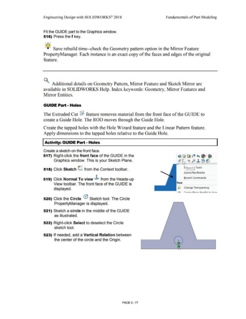
520) Click the Circle 0 Sketch tool. The Circle
PropertyManager is displayed.
521) Sketch a circle in the middle of the GUIDE
as illustrated.
522) Right-click Select to deselect the Circle
sketch tool.
523) If needed, add a Vertical Relation between
the center of the circle and the Origin. 0
PAGE2 - 77