
Page 145 - Subyek Computer Aided Design - [David Planchard] Engineering Design with SOLIDWORKS
P. 145
Engineering Design with SOLIDWORKS® 201 8 Fundamentals of Part Modeling
Activity: GUIDE Part· Extruded Cut Slot Profile
Display a Top view. Create the Slot sketch on the top right face of the model.
476) Click Top view @.
477) Right-click the top right face of the GUIDE in the Graphics eD C2 ~ le +, e· ~~
window. - - C!1I , feJ> ® ~
478) Click Sketch e=_ from the Context toolbar. The Sketch [si~tch.f n Tools
Zoom/Pan/Rotate
toolbar is displayed.
Becent Commands
Apply the Straight Slot Sketch tool. The Straight Slot Sketch tool Face
requires three points, ... ., Change Transparency
..----. r.iii Create e1ane Parallel to Screen
479) Click the Straight Slot Sketch O tool from the
Feature (Base Extrude)
Consolidated Slot toolbar as illustrated. The Slot
PropertyManager is displayed.
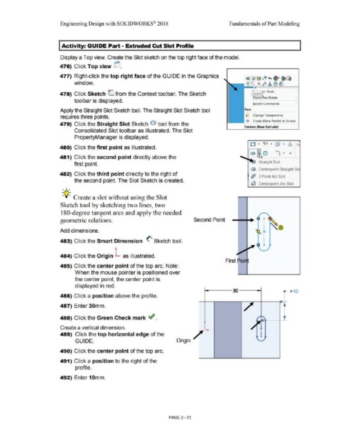
480) Click the first point as illustrated.
481) Click the second point directly above the
Straight Slot
first point.
@ Centerpoint Straight Sia
482) Click the third point directly to the right of
(jJJ 3 Point Arc Slot
the second point. The Slot Sketch is created.
~ Centerpoint Arc Slot
' I /
;Q-;, Create a slot without using the Slot
Sketch tool by sketching two lines, two
180-degree tangent arcs and apply the needed
geometric relations. Second Point +
@
Add dimensions.
483) Click the Smart Dimension <' Sketch tool.
+
484) Click the Origin L as illustrated.
485) Click the center point of the top arc. Note:
When the mouse pointer is positioned over
the center point, the center point is
displayed in red.
30 c- 10
486) Click a position above the profile.
/
487) Enter 30mm.
-
488) Click the Green Check mark ~ . ' '
--
Create a vertical dimension. l
489) Click the top horizontal edge of the 1
GUIDE. Origin/
490) Click the center point of the top arc.
491) Click a position to the right of the
profile.
492) Enter 10mm.
PAGE 2 - 73