
Page 143 - Subyek Computer Aided Design - [David Planchard] Engineering Design with SOLIDWORKS
P. 143
Engineering Design with SOLIDWORKS® 2018 Fundamentals of Part Modeling
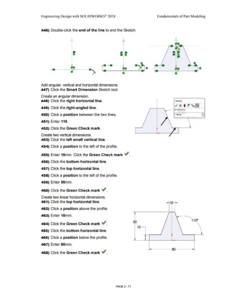
446) Double-click the end of the line to end the Sketch.
_L
....._
I
•
I
•
I
•
•••
I
I
•' •
I
•
I
•
- •D
Add angular, vertical and horizontal dimensions.
447) Click the Smart Dimension Sketch tool.
Create an angular dimension.
448) Click the right horizontal line. r Modify
~ x I ~ ~~~
449) Click the right-angled line. -
__ --t D1~Sketch1
- Angle! ..
450) Click a position between the two lines. 11~eg •
~ I
451) Enter 110.
452) Click the Green Check mark.
Create two vertical dimensions.
453) Click the left small vertical line.
454) Click a position to the left of the profile.
455) Enter 1 Omm. Click the Green Check mark ~ .
456) Click the bottom horizontal line.
457) Click the top horizontal line.
458) Click a position to the left of the profile.
459) Enter 50mm.
460) Click the Green Check mark ~ .
Create two linear horizontal dimensions.
461) Click the top horizontal line.
462) Click a position above the profile.
463) Enter 10mm.
110°
50
464) Click the Green Check mark ~ .
10 ~
465) Click the bottom horizontal line.
466) Click a position below the profile.
467) Enter 80mm.
468) Click the Green Check mark ~ .
PAGE2 - 71