
Page 139 - Subyek Computer Aided Design - [David Planchard] Engineering Design with SOLIDWORKS
P. 139
Engineering Design with SOLIDWORKS® 2018 Fundamentals of Part Modeling
~ ~!i!8 $ ~ >
t:~ 0
y
~ Review of the ROD Part ~ ROD (Default< <Default> _Disp
• ~ I History
The ROD part utilized an Extruded Boss/Base feature with a circular ~ Sensors
profile sketched on the Front Plane. Linear and diameter dimensions • fA'J Annotations
~ Equations
corresponded to the customer's requirements. o-
~:o Material <not specified>
dJ Front Plane
The Chamfer feature removed the front circular edge. The Chamfer
dJ Top Plane
feature required an edge, distance and angle parameters. The dJ Right Plane
Extruded Cut feature utilized a converted edge of the Base Extrude L Origin
• djJ Base Extrude
feature to form the Keyway Cut. Reuse geometry with the Convert C.. Sketch1
Entity Sketch tool. • ~ Front Cut
C.. Sketch7
You utilized the Hole Wizard feature for a simple hole on the front ... ~ Front Hole
C.. Sketch2
face to create the Front Hole. You reused geometry. The Front Hole C.. sketch3
was copied and pasted to the back face to create the Back Hole. The ~ Chamfer1
... ~ Keyway Cut
Back Hole dimensions were modified. The Display\Delete Sketch
C.. Keyway
Tool deleted dangling dimensions of the copied feature. You inserted ... ~ 04.0 (4) Back Hole
an Extruded Cut feature by moving the Rollback bar to a new C.. SketchS
C.. Sketch6
position in the FeatureManager. You recovered from the errors that
occurred with Edit Feature, Edit Sketch, and Edit Sketch plane tools
by redefining geometry.
GUIDE Part Overview
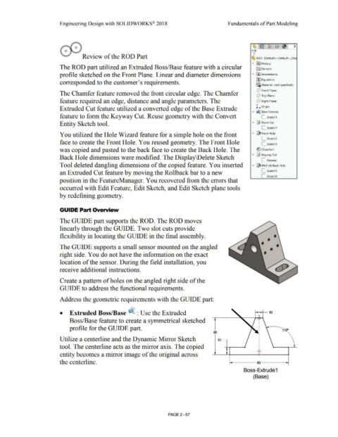
The GUIDE part supports the ROD. The ROD moves
linearly through the GUIDE. Two slot cuts provide
flexibility in locating the GUIDE in the final assembly. •
• •
The GUIDE supports a small sensor mounted on the angled • •
right side. You do not have the information on the exact
location of the sensor. During the field installation, you
receive additional instructions.
Create a pattern of holes on the angled right side of the
GUIDE to address the functional requirements.
Address the geometric requirements with the GUIDE part:
• Extruded Boss/Base ~ : Use the Extruded rr•o
--,.....,tH
Boss/Base feature to create a symmetrical sketched I
I
profile for the GUIDE part. I
I 1100
50
I
I
Utilize a centerline and the Dynamic Mirror Sketch 10~ I
tool. The centerline acts as the mirror axis. The copied
entity becomes a mirror image of the original across '
the centerline. - 1- - oo- - -1
Boss-Extrude 1
(Base)
PAGE2 - 67