
Page 138 - Subyek Computer Aided Design - [David Planchard] Engineering Design with SOLIDWORKS
P. 138
FundamentaJs of Part Modeling Engineering Design with SOLIDWORKS 2018
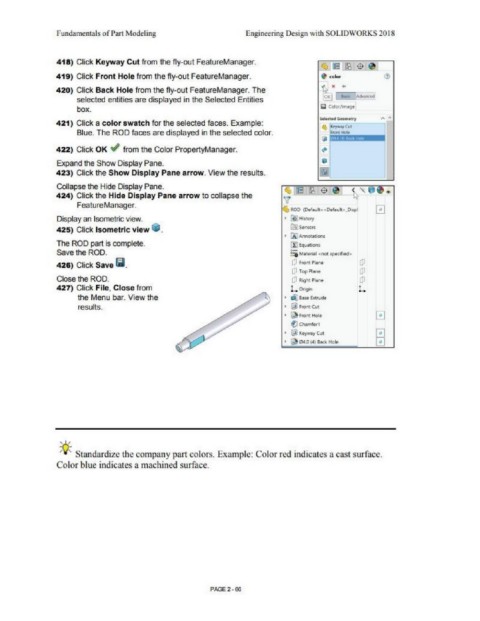
418) Click Keyway Cut from the fly-out FealureManager.
419) Click Front Hole from the fly-out FeatureManager.
420) Click Back Hole from lhe fly-out FeatureManager. The
selected entities are displayed in the Selected Entities
box.
Sdt«.i Gfoll\eiry A ;.
421) Click a color swatch for the selected faces. Example:
• l:q,q,JCIII
Blue. The ROD faces are displayed in the selected color. '""'"""
.. lm'ii:Jmmm-• 1
422) Click OK ~ from the Color PropertyManager. ~
•
Expand the Show Display Pane. ,.
423) Click the Show Display Pane arrow. View the results.
Collapse the Hide Display Pane.
,1rl% ~ $ ~ · h-, Ul 'C'~
424) Click the Hide Display Pane arrow to collapse the v
FeatureManager. 0
I ROD (~f..ilt<<Oeleult>_Di~ I
Display an Isometric view. • ~ Histol)'
425) Click Isometric view Ii. ~Stnson
• 00 A11t1CM1ioM
The ROD part is complete. -
[t'j Equlltiorlj
Save the ROD. ~ M11ttrlal <not speclfotd>
426) Click Save 11.1. Q ~ront Plar. [P
(lJ Top Plane (P
Close the ROD. CJ Righl Pl•nt (P
427) Click File, Close from L.Oo9ln L.
the Menu bar. View the • -.1 ec.t, btNde
results. ' @ F«ll"l:(ut
• ~ Front Hole El
(l: Cholm.forl
' !al KC"(Ney(ut
• ~ 04.0 (,4) B«k tiOlt
' . /
iJ:. Standardize the company part colors. Example: Color red indicates a cast surfac.e.
Color blue indicates a machined surface.
PAGE2 · 66