Page 133 - Subyek Computer Aided Design - [David Planchard] Engineering Design with SOLIDWORKS
P. 133

Engineering Design with SOLIDWORKS® 2018                                                                                                                                                               Fundamentals of Part Modeling


                                                                        Fit the ROD to the Graphics window.


                                                                        364) Press the f key.


                                                                                                                                                                                                                                                                                                                                              ~- · (/) 7
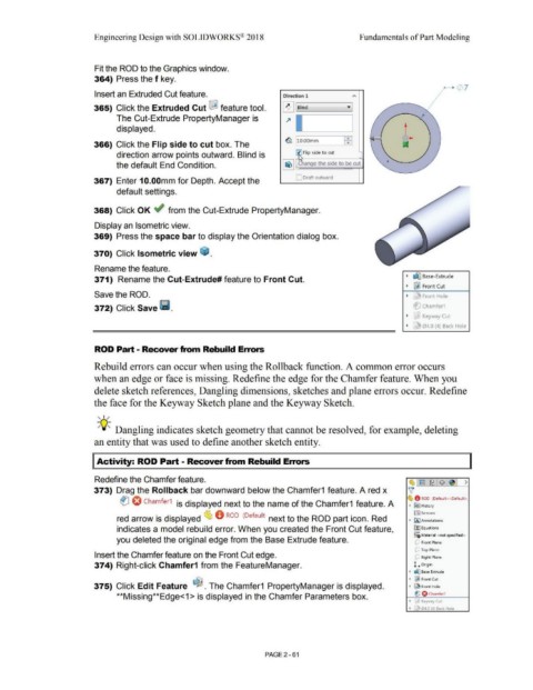
                                                                        Insert an Extruded Cut feature.                                                                                                               Direction 1


                                                                       365) Click the Extruded Cut l&l feature tool.                                                                                                 ~ ..__I Bl_ind ___ _____,• ]


                                                                                        The Cut-Extrude PropertyManager is                                                                                              ~


                                                                                        displayed.                                                                                                                                                                                                               t


                                                                                                                                                                                                                       ~ 110.oomm                                  ~I                                               ....
                                                                       366) Click the Flip side to cut box. The


                                                                                        direction arrow points outward. Blind is                                                                                                     Flip side to cut


                                                                                        the default End Condition.


                                                                                                                                                                                                                               C Draft outward
                                                                       367)  Enter 1 O.OOmm for Depth. Accept the


                                                                                        default settings.


                                                                       368) Click OK ~ from the Cut-Extrude PropertyManager.


                                                                        Display an Isometric view.


                                                                       369)  Press the space bar to display the Orientation dialog box.


                                                                       370) Click Isometric view ~ .


                                                                        Rename the feature.


                                                                                                                                                                                                                                                                                                                  ~  ~ Base-Extrude
                                                                        371)  Rename the Cut-Extrude# feature to Front Cut.

                                                                                                                                                                                                                                                                                                                  ~  ~ Front Cut

                                                                        Save the ROD.                                                                                                                                                                                                                             ~  r ~ Front Hole


                                                                        372) Click Save 111.                                                                                                                                                                                                                            et:) Chamfer1


                                                                                                                                                                                                                                                                                                                  ~  ~ Keyway Cut


                                                                                                                                                                                                                                                                                                                  ~  r J  04.0 (4)  Back Hole


                                                                        ROD Part - Recover from Rebuild Errors


                                                                        Rebuild errors can occur when using the Rollback function. A common error occurs


                                                                       when an edge or face is missing. Redefine the edge for the Chamfer feature. When you


                                                                        delete sketch references, Dangling dimensions, sketches and plane errors occur. Redefine


                                                                        the face for the Keyway Sketch plane and the Keyway Sketch.


                                                                          , ,/


                                                                          -;Q~ Dangling indicates sketch geometry that cannot be resolved, for example, deleting


                                                                        an entity that was used to define another sketch entity.


                                                                         Activity: ROD Part - Recover from Rebuild Errors


                                                                        Redefine the Chamfer feature.                                                                                                                                                                                                               (1, ~ 1~ $~  >


                                                                       373)  Drag the Rollback bar downward below the Chamfer1  feature. A red x                                                                                                                                                                    v'


                                                                                                                                                                                                                                                                                                                   ~ 0  ROD  (Default<<Default>
                                                                                           tlJ O Chamfer1  is displayed next to the name of the Chamfer1  feature. A                                                                                                                                                •  IE>) History


                                                                                                                                                                                                                                                                                                                        !al Sensors
                                                                                        red arrow is displayed ~ 0  ROD  (Default· next to the ROD part icon. Red                                                                                                                                                   • IAJ Annotations


                                                                                        indicates a model rebuild error. When you created the Front Cut feature,                                                                                                                                                        o-
                                                                                                                                                                                                                                                                                                                        ll::] Equations
                                                                                                                                                                                                                                                                                                                        ::o Material  <not specified>
                                                                                        you deleted the original edge from the Base Extrude feature.                                                                                                                                                                     uJ  Front Plane


                                                                                                                                                                                                                                                                                                                         dJ  Top Plane
                                                                        Insert the Chamfer feature on the Front Cut edge.                                                                                                                                                                                                dJ  Right Plane


                                                                        374) Right-click Chamfer1 from the FeatureManager.                                                                                                                                                                                              L    orlgin


                                                                                                                                                                                                                                                                                                                    • d'.J Base Extrude

                                                                                                                                                                                                                                                                                                                    •  ~ Front Cut
                                                                       375) Click Edit Feature  ~ . The Chamfer1  PropertyManager is displayed.                                                                                                                                                                     •         Front Hole


                                                                                        **Missing**Edge<1 > is displayed in the Chamfer Parameters box.                                                                                                                                                                 tJ O Chamfer1

                                                                                                                                                                                                                                                                                                                    •  '3  Keyway Cut


                                                                                                                                                                                                                                                                                                                    •        04.0 (4) Back Hole


                                                                                                                                                                                                        PAGE2 - 61
   128   129   130   131   132   133   134   135   136   137   138