
Page 137 - Subyek Computer Aided Design - [David Planchard] Engineering Design with SOLIDWORKS
P. 137
Engineering Design with SOLIDWORKS® 2018 Fundamentals of Part Modeling
Modify the depth of the Back Hole.
406) Right-click 04.0 (4) Back Hole from the FeatureManager.
End Condition ~
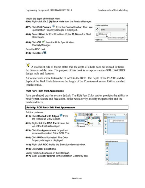
407) Click Edit Feature ~ from the Context toolbar. The Hole
Specification PropertyManager is displayed. ~ ~ nd ~
- ;..
408) Select Blind for End Condition. Enter 20.00mm for Blind L. 20.00mm - ..,
Hole Depth. Blind Hole Depth
Options ~
409) Click OK ~ from the Hole Specification
PropertyManager.
Save the ROD part.
410) Click Save 111.
, ,/
-;Q~ A machinist rule of thumb states that the depth of a hole does not exceed 10 times
the diameter of the hole. The purpose of this book is to expose various SOLIDWORKS
design tools and features.
A Countersunk screw fastens the PLATE to the ROD. The depth of the PLATE and the
depth of the Back Hole determine the length of the Countersunk screw. Utilize standard
length screws.
ROD Part - Edit Part Appearance
Parts are shaded gray by system default. The Edit Part Color option provides the ability to
modify part, feature and face color. In the next activity, modify the part color and the
machined faces.
I Activity: ROD Part - Edit Part Appearance
Edit the part color.
Selected Geometry A "'
411) Click Shaded with Edges e from
l ~ J ROD.SLDPRT I
the Heads-up View toolbar.
@] ~ lear Selections
412) Right-click the ROD Part icon at the \)
top of the FeatureManager. ~
@]
413) Click the Appearances drop-down
arrow as illustrated. Click ROD. The ~
414) Click ROD as illustrated. The Color
PropertyManager is displayed. Selected Geometry A
415) Right-click ROD inside the Selection Geometry box. ~
~
416) Click Clear Selections.
~
Modify machined surfaces on the ROD part.
417) Click Select Features in the Selection Geometry box. ~
~
Select Features
earan1 .P
PAGE2 - 65