
Page 141 - Subyek Computer Aided Design - [David Planchard] Engineering Design with SOLIDWORKS
P. 141
Engineering Design with SOLIDWORKS® 2018 Fundamentals of Part Modeling
GUIDE Part - Extruded Boss/Base Feature and Dynamic Mirror
The GUIDE utilizes an Extruded Boss/Base feature. What is the Sketch plane? Answer:
The Front Plane is the Sketch plane. The Mid Plane End Condition extrudes the sketch
symmetric about the Front Plane.
How do you sketch a symmetrical 2D profile? Answer: Use a sketched centerline and the
Dynamic Mirror Sketch tool.
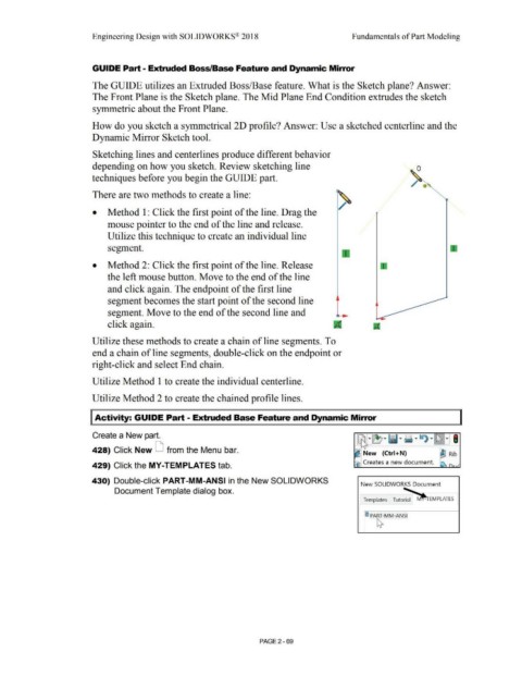
Sketching lines and centerlines produce different behavior
depending on how you sketch. Review sketching line
techniques before you begin the GUIDE part.
There are two methods to create a line:
• Method 1: Click the first point of the line. Drag the
mouse pointer to the end of the line and release.
Utilize this technique to create an individual line
segment.
• Method 2: Click the first point of the line. Release
the left mouse button. Move to the end of the line
and click again. The endpoint of the first line
segment becomes the start point of the second line
segment. Move to the end of the second line and
click again.
Utilize these methods to create a chain of line segments. To
end a chain of line segments, double-click on the endpoint or
right-click and select End chain.
Utilize Method 1 to create the individual centerline.
Utilize Method 2 to create the chained profile lines.
Activity: GUIDE Part - Extruded Base Feature and Dynamic Mirror
Create a New part.
428) Click New LJ from the Menu bar.
New (Ctrl+N) ~ Rib
Creates a new document.
429) Click the MY-TEMPLATES tab.
430) Double-click PART-MM-ANSI in the New SOLIDWORKS
New SOLIDWORKS Document
Document Template dialog box.
~ PART-MM-ANSI
~
PAGE2 - 69