
Page 146 - Subyek Computer Aided Design - [David Planchard] Engineering Design with SOLIDWORKS
P. 146
Funda1nentals of Part Modeling Engineering Design with SOLIDWORKS 2018
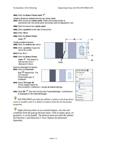
493) Click the Green Check mark ~ .
Create a dimension between the two arc center points.
494) Click the top arc center point. When the mouse pointer is
positioned over the center point, the center point is displayed in red.
495) Click the second arc center point.
496) Click a position to the right of the profile.
497) Enter 10mm.
498) Click the Green Check
mark ..; . i------- 30 ------<i--i ~ 10
Create a radial dimension.
499) Click the bottom arc radius.
500) Click a position diagonally
below the profile. l
1---..--------+--+-
501) Enter 3mm.
.___ 10
502) Click the Green Check
mark .; . The Sketch is
--- R3
fully defined and is Origin
displayed in black.
Insert an Extruded Cut feature.
503) Click the Extruded
~Jtrnl~:$ 1~1
Cut ~ feature tool. The ~ Cut-Extrude CV
+-
Cut-Extrude I .., x @>
PropertyManager is r From A
displayed. lsk~tch Plane v j
Direction 1 "'
504) Select Through All ~ T rough All v
(Think Design Intent) for
l" End Condition : Through All
End Condition in Direction1. Accept all default settings.
O Flip side to cul
505) Click OK ~ from the Cut-Extrude PropertyManager. Cut-Extrude1
is displayed in the FeatureManager. Draft outward
, ,/ O Direction 2 v
O Thin Feature v
-;Q-;, SOLIDWORKS provides the ability to select a unit drop-down Selected Contours v
menu to modify units in a sketch or feature from the set document
properties.
, ,/
-;Q-;, Right-click anywhere on an extruded feature; view the end
conditions from the pop-up shortcut menu. Click in empty space, on
geometry, or on the handle. The shortcut menu provides the options
for Direction I and Direction 2. Note: Options are document
dependent.
PAGE2-74