
Page 151 - Subyek Computer Aided Design - [David Planchard] Engineering Design with SOLIDWORKS
P. 151
Engineering Design with SOLIDWORKS® 2018 Fundamentals of Part Modeling
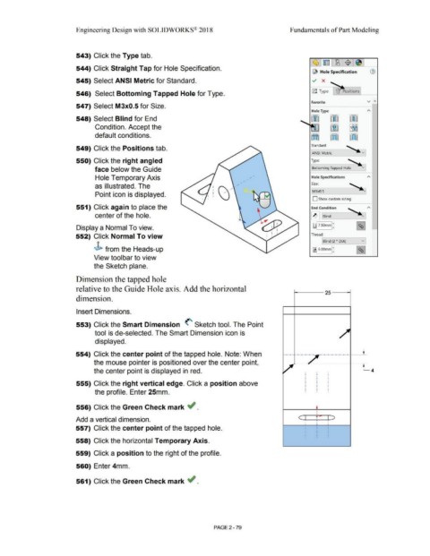
543) Click the Type tab.
544) Click Straight Tap for Hole Specification.
@ Hole Specification
545) Select ANSI Metric for Standard. ../ x ~-~
546) Select Bottoming Tapped Hole for Type. !JJ Type I lJ Positions
Favorite V A
547) Select M3x0.5 for Size.
Hole Type
548) Select Blind for End ~ !J]
..__~·~ i [rm
Condition. Accept the
default conditions. Kt)] [ffl
Standard:
549) Click the Positions tab.
LANSI Metric
550) Click the right angled Type: '
face below the Guide ~Bottoming Tapped Hole v]
Hole Temporary Axis Hole Specifications
as illustrated. The Size: - ~
M3x0.5
Point icon is displayed.
D Show custom sizing
551) Click again to place the End Condition
center of the hole. ~ Blind
Display a Normal To view. ~ 7.SOmml:
552) Click Normal To view Thread:
Blind (2 * DIA) v]
J> from the Heads-up ~ 6.00mml: I %j
View toolbar to view
the Sketch plane.
Dimension the tapped hole
relative to the Guide Hole axis. Add the horizontal
t----- 25 - --i
dimension.
Insert Dimensions.
553) Click the Smart Dimension <' Sketch tool. The Point
tool is de-selected. The Smart Dimension icon is
displayed.
554) Click the center point of the tapped hole. Note: When
the mouse pointer is positioned over the center point, *-~ :.__-----I-~
the center point is displayed in red.
555) Click the right vertical edge. Click a position above
the profile. Enter 25mm.
556) Click the Green Check mark ~ . •
c t p ~
Add a vertical dimension. I I
.
I •
557) Click the center point of the tapped hole.
558) Click the horizontal Temporary Axis.
559) Click a position to the right of the profile.
560) Enter 4mm.
561) Click the Green Check mark ~ .
PAGE2 - 79