
Page 150 - Subyek Computer Aided Design - [David Planchard] Engineering Design with SOLIDWORKS
P. 150
FundamentaJs of Part Modeling Engineering Design with SOLIDWORKS 2018
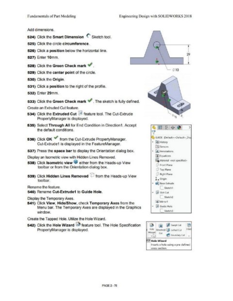
Add dimensions.
524) Click the Smart Dimension (' Sketch tool.
525) Click the circle circumference.
526) Click a position below the horizontal line.
29
527) Enter 10mm.
I
528) Click the Green Check mark ,,I_
529) Click the center point of the circle.
530) Click the Origin.
531) Click a position to the right of the profile.
532) Enler 29mm.
533) Click the Green Check mark ,,I_ The sketch is fully defined.
Create an Extruded Cut feature.
534) Click the Extruded Cut ~ feature tool. The Cut-Extrude
PropertyManager is displayed.
535) Select Through All for End Condition in Direction1. Accept
the default conditions.
GUIDE iOef<1uh«Defautt),_Ols
536) Click OK ~ from the Cut-Extrude PropertyManager.
• Ii) History
Cut-Extrude1 is displayed in the FealureManager.
[lIJ Sensors
537) Press the space bar to display the Orientation dialog box. • Ci) A.nnol"51ions
u:)EquaUom
Display an Isometric view with Hidden Lines Removed.
!;a Miltertill <not specified>
538) Click Isometric view * either from the Heads-up View
CJ Front Pl.1nt
toolbar or from the Orientation dialog box.
CJ Top Plillle
[? Right Pl"51lt
539) Click Hidden Lines Removed © from the Heads-up View
L eng.n
tool bar.
QJ} Bilse Extn..ide
Rename the feature. c_ Sk~tch1
540) Rename Cut-Extrude1 to Guide Hole. £ij Slot Cut
C.sketc:h2
Display the Temporary Pvt.es.
541) Click View, Hide/Show, check Temporary Axes from the Ci:)Mlrrorl
Menu bar. The Temporary Pvt.es are displayed in the Graphics .... @') Guide Hole
window. [__ Sk.$t,h)
Create the Tapped Hole. Utilize the Hole Wizard.
542) Click the Hole Wizard ~ feature tool. The Hole Specification
PropertyManager is displayed.
!,'Of Hol~ Wiurd
Inserts a hole vsing a pre-defined
cross-section.
PAGE2· 78