
Page 147 - Subyek Computer Aided Design - [David Planchard] Engineering Design with SOLIDWORKS
P. 147
Engineering Design with SOLIDWORKS® 2018 Fundamentals of Part Modeling
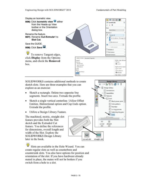
Display an Isometric view.
506) Click Isometric view ~ either
fj Cut-Extrude
from the Heads-up View ., x ®
toolbar or the Orientation From
dialog box. Sketch Plane v
Direction 1
Rename the feature.
~ .! rough All v
507) Rename Cut-Extrude1 to
l4 End Condition : Through All
Slot Cut.
O Flip side to cut
Save the GUIDE. •
•
508) Click Save lii. Draft outward
, ,/ O Direction 2 v
O Thin Feature v
-;Q~ To remove Tangent edges, Selected Contours v
click Display from the Options System Options Document Properties
menu, and check the Removed General Hidden edges displaye
Drawings Osolid
box. r Display Style @ Dashed
I Area Hatch/Fill
Performance Part/Assembly tangent
Colors O As visible
Sketch
0As phantom
- ons/Snaps
@ Removed
~n Edge display in shaded
SOLIDWORKS contains additional methods to create « Design Library
sketch slots. Here are three examples that you can
explore as an exercise:
• Sketch a rectangle. Delete two opposite line
segments. Insert two arcs. Extrude the profile.
• Sketch a single vertical centerline. Utilize Offset le; fluid power ports
Entities, Bidirectional option and Cap Ends option. D hole patterns
Extrude the profile. Q keyways
D o-ring grooves
• Utilize a Design Library Feature. D retaining ring gro<
The machined, metric, straight slot
< >
feature provides both the Slot
c - O
sketch and the Extruded Cut curved straight
feature. You define the references slot slot
for dimensions, overall length and
width of the Slot. Explore the
SOLIDWORKS Design Library
later in the book. curved slot straight slot
,,/
-;Q~ Slots are available in the Hole Wizard. You can
create regular slots as well as counterbore and
countersink slots. You also have options for position and
orientation of the slot. If you have hardware already
mated in place, the mates will not be broken if you
switch from a hole to a slot.
PAGE2 - 75