Page 144 - Subyek Computer Aided Design - [David Planchard] Engineering Design with SOLIDWORKS
P. 144

Fundamentals of Part Modeling                                                                                                                                 Engineering Design with SOLIDWORKS 2018


                                                   , ,/


                                                  ;Q~ Select edges instead of points to create linear


                                                dimensions. Points are removed when Fillet and                                                                                                                                                                                               lo
                                                                                                                                                                                                                                                                                               •
                                                                                                                                                                                                                                                                                               I
                                                Chamfer features are added.                                                                                                                                                                                                                    •


                                                   , ,/                                                                                                                                                                                                                                                      \


                                                                                                                                                                                                                                                                                          ,./':.
                                                  ;Q~ Dimension angles, smaller line segments, and then                                                                                                                                                                                 .  I


                                                                                                                                                                                                                                                                                               •
                                                larger line segments to maintain the profile shape.                                                                                                                                                                                            I

                                                                                                                                                                                                                                                                                               •


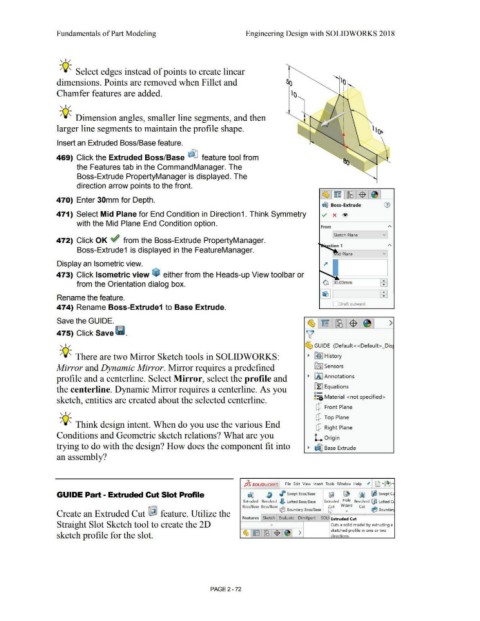
                                                Insert an Extruded Boss/Base feature.


                                                469) Click the Extruded Boss/Base OT]  feature tool from


                                                                 the Features tab in the CommandManager. The


                                                                 Boss-Extrude PropertyManager is displayed. The


                                                                 direction arrow points to the front.


                                                470)  Enter 30mm for Depth.


                                                                                                                                                                                                                                                                              dIJ  Boss-Extrude                                  (i)


                                                471) Select Mid Plane for End Condition in Direction1. Think Symmetry                                                                                                                                                        ./  x  ®


                                                                 with the Mid Plane End Condition option.
                                                                                                                                                                                                                                                                             From                                                   A

                                                                                                                                                                                                                                                                                                                                v]
                                                                                                                                                                                                                                                                                       Sketch Plane
                                                472) Click OK .; from the Boss-Extrude PropertyManager.

                                                                                                                                                                                                                                                                                                                                    A
                                                                 Boss-Extrude1  is displayed in the FeatureManager.
                                                                                                                                                                                                                                                                                                                                v


                                                Display an Isometric view.


                                                473) Click Isometric view ~ either from the Heads-up View toolbar or


                                                                 from the Orientation dialog box.                                                                                                                                                                             ~ ~ O.OOmm                                     ~


                                                                                                                                                                                                                                                                            ~ I                                               WI

                                                Rename the feature.


                                                                                                                                                                                                                                                                                            Draft outward
                                                474) Rename Boss-Extrude1  to Base Extrude.


                                                Save the GUIDE.                                                                                                                                                                                                  ~ ~ ~ $- ~  >


                                                475) Click Save Ii.                                                                                                                                                                                             v


                                                   , ,/                                                                                                                                                                                                        ~ GUIDE  (Default< <Default> _Dis


                                                  -;Q~ There are two Mirror Sketch tools in SOLIDWORKS:                                                                                                                                                          •  ~I History


                                                Mirror and Dynamic Mirror. Mirror requires a predefined                                                                                                                                                                lr0::] Sensors


                                                profile and a centerline. Select Mirror, select the profile and                                                                                                                                                  •  (A I Annotations


                                                the centerline. Dynamic Mirror requires a centerline. As you                                                                                                                                                           i:I:I Equations

                                                                                                                                                                                                                                                                       o-

                                                sketch, entities are created about the selected centerline.                                                                                                                                                            ;::a Material  <not specified>


                                                                                                                                                                                                                                                                        Q Front Plane
                                                   , ,/


                                                                                                                                                                                                                                                                        Q Top Plane

                                                  -;Q~ Think design intent. When do you use the various End

                                                                                                                                                                                                                                                                        Q Right Plane

                                                Conditions and Geometric sketch relations? What are you                                                                                                                                                                l. Origin


                                                trying to do with the design? How does the component fit into                                                                                                                                                     •  ~ Base Extrude


                                                an assembly?


                                                                                                                                                                                                              7.                               File  Edit  View  Insert  Tools  Window  Help  Jt  D .e,;.
                                                                                                                                                                                                            JjS SOLIDWORKS


                                                GUIDE Part - Extruded Cut Slot Profile                                                                                                                         ~               ~          I  Swept Boss/ Base                      ~           ~  fjijl                ~ SweptC1


                                                                                                                                                                                                            Extruded  Revolved  ~ Lofted Boss/ Base                            Extruded  Hole  Revolved ('.jjll  Lofted c,
                                                                                                                                                                                                           Boss/ Base  Boss/ Base  ~                                                         Wizard          Cut       ~
                                                                                                                                                                                                                                                Boundary Boss/ Base               ~ t            •                           Boundar
                                                Create an Extruded Cut ~  feature. Utilize the

                                                                                                                                                                                                           Features  Sketch  Evaluate  DimXpert                              SOLi    Extruded Cut

                                                Straight Slot Sketch tool to create the 20                                                                                                                                        f)                                                 Cuts a solid model by extruding a

                                                                                                                                                                                                            ~1~1~:$ 1~1                                                              sketched profile in one or two
                                                                                                                                                                                                                                                          >
                                                sketch profile for the slot.                                                                                                                                                                                                         directions.


                                                                                                                                                                                PAGE2 - 72
   139   140   141   142   143   144   145   146   147   148   149