
Page 130 - Subyek Computer Aided Design - [David Planchard] Engineering Design with SOLIDWORKS
P. 130
Fundamentals of Part Modeling Engineering Design with SOLIDWORKS 2018
ROD Part - Copy/Paste Feature
The Copy and Paste feature allows you to copy selected sketches and features from one
face to another face or from one model to different models.
The ROD requires an additional hole on the back face. Copy the Front Hole feature to the
back face. Edit the sketch and modify the dimensions and geometric relations.
I Activity: ROD Part - Copy/Paste Feature
Copy the Front Hole to the Back Face.
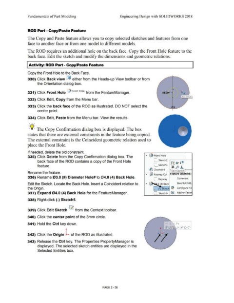
330) Click Back view dj either from the Heads-up View toolbar or from
the Orientation dialog box.
331) Click Front Hole ~ Front Hole from the FeatureManager. 118.00°
Base Extrude
332) Click Edit, Copy from the Menu bar.
333) Click the back face of the ROD as illustrated. DO NOT select the
center point.
334) Click Edit, Paste from the Menu bar. View the results.
, 1 /
-;Q~ The Copy Confirmation dialog box is displayed. The box
states that there are external constraints in the feature being copied.
The external constraint is the Coincident geometric relation used to
place the Front Hole.
If needed, delete the old constraint.
335) Click Delete from the Copy Confirmation dialog box. The ..,.. ~ Front Hole
back face of the ROD contains a copy of the Front Hole
feature. L_ Sketch3 = t
~ Chamfer 1 Edit Sketch 1--t
Rename the feature.
..,.. ~ Keyway Cut Fea ure etchS)
336) Rename 03.0 {#) Diameter Hole# to 04.0 (4) Back Hole.
C_ Keyway Comment
Edit the Sketch. Locate the Back Hole. Insert a Coincident relation to ., .. ~--'""1~ .0 (4) Back Earent/Child.
the Origin. C_ (-) Sketch ~ Configure Fe
337) Expand 04.0 (4) Back Hole for the FeatureManager. C_ Sketch6 ~ Add to Favor
338) Right-click{-) Sketch5.
339) Click Edit Sketch ~ from the Context toolbar.
340) Click the center point of the 3mm circle.
341) Hold the Ctrl key down. - I r-i
• ['.@ 1: 1 ~p; fe) ~ t> <'
342) Click the Origin L of the ROD as illustrated.
343) Release the Ctrl key. The Properties PropertyManager is
displayed. The selected sketch entities are displayed in the
Selected Entities box.
PAGE2 - 58