
Page 127 - Subyek Computer Aided Design - [David Planchard] Engineering Design with SOLIDWORKS
P. 127
Engineering Design with SOLIDWORKS® 2018 Fundamentals of Part Modeling
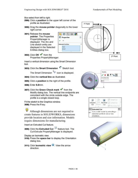
Box-select from left to right.
299) Click a position to the upper left corner of the
profile as illustrated. 1 Point
81
1~----t---'"J.,___- - - - - - - - - -
300) Drag the mouse pointer diagonally to the lower I
I
right corner. I
I
I
301) Release the mouse I
I I
pointer. The Properties G) t
~ Properties I
PropertyManager is .., .... - -- ------- ----~ -L - 1--- -- -- ..
I
I
displayed. The Arc and
Line sketch entity are Selected Entities
displayed in the Selected Arc2
Line1
Entities dialog box.
•
1----------· ... _
302) Click OK ~ from the
2nd Point
Properties PropertyManager.
Insert a vertical dimension using the Smart Dimension
tool.
303) Click the Smart Dimension (' Sketch tool.
Modify
The Smart Dimension ~<' icon is displayed.
304) Click the vertical line as illustrated.
D1 @Sketch4
-
•
305) Click a position to the right of the profile. ~mm ...
306) Enter 6.0mm.
307) Click the Green Check mark ~ from the
Modify dialog box. The vertical line endpoints are
coincident with the circle outside edge. The
profile is a single closed loop.
~ ~ Swept Cut
Fit the sketch to the Graphics window. Yolt-> F
Ext~ed Revolved Lofted Cut
308) Press the f key. 'izdr - Cut
.... BoLindary Cut
, ,/
OLI Extruded Cut D
-;Q~ Although dimensions are not required to rt Cuts a solid model by extruding a
1
create features in SOLIDWORKS, dimensions sketched profile in one or two
directions.
provide location and size information. Models
require dimensions for manufacturing.
Insert an Extruded Cut feature.
309) Click the Extruded Cut ~ feature tool. The
Cut-Extrude PropertyManager is displayed.
Display an Isometric view.
31 O) Press the space bar to display the Orientation
dialog box.
311) Click Isometric view (o. View the arrow
direction. ....
PAGE 2 - 55