
Page 123 - Subyek Computer Aided Design - [David Planchard] Engineering Design with SOLIDWORKS
P. 123
Engineering Design with SOLIDWORKS® 2018 Fundamentals of Part Modeling
263) Expand Diameter Hole1 in the FeatureManager. View the two ~ l!rn ~!$ 1~ 1 :
sketches. Both sketches are fully defined.
v
Display an Isometric view with Hidden Lines Visible. ~ ROD (Default < <Default> _Di•
264) Press the space bar to display the Orientation dialog box. ~ ~I History
~ Sensors
265) Click Isometric view ~ . ~ IA] Annotations
[t) Equations
o-
266) Click Hidden Lines Visible ® from the Heads-up View toolbar. ~::i) Material <not specified>
[P Front Plane
Rename Diameter Hole1.
[P Top Plane
267) Rename Diameter Hole1 to Front Hole.
[P Right Plane
Save the ROD. !.... Origin
268) Click Save llll. .... ~ Base Extrude
C_ Sketch1
.... ~ Front Hole
The Hole Wizard ~ feature creates either a 2D or 3D sketch for the
L_ Sketch2
placement of the hole in the F eatureManager. You can consecutively L_ Sketch3
place multiple holes of the same type. The Hole Wizard creates 2D
sketches for holes unless you select a non-planar face or click the 3D
Sketch button in the Hole Position PropertyManager.
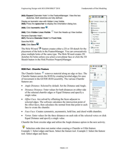
ROD Part - Chamfer Feature ~ Chamfer
., x
The Chamfer feature ei removes material along an edge or face. The Chamfer Type A
v i:,- ~
Chamfer feature assists the ROD by creating beveled edges for ease
~ ~
of movement in the GUIDE-ROD assembly. The various Chamfer
Items To Chamfer A
features are:
• Angle Distance. Selected by default. Set the Distance and Angle. L -
0 Tangent propagation
• Distance Distance. Enter values for both distances on either side @ Full preview
O Partial preview
of the selected chamfer edges or Equal Distance and specify a 0 No preview
single value. Chamfer Parameters A
O Flip direction
£
• Offset Face. Are solved by offsetting the faces adjacent to 0 ~ O.OOmm F
selected edges. The software calculates the intersection point of t.f 145.00deg
Chamfer Options I A I
the offset faces, then calculates the normal from that point to each 0 Select through faces
face to create the chamfer. 0 Keep features
• Face Face. Creates symmetric, asymmetric, hold line, and chord width chamfers.
• Vertex. Enter values for the three distances on each side of the selected vertex or click
Equal Distance and specify a single value.
Chamfer the front circular edge and utilize the Angle distance option in the next activity.
, ,/
-;Q~ Selection order does not matter when creating a Chamfer or Fillet feature.
Example 1: Select edges and faces. Select the feature tool. Example 2: Select the feature
tool. Select edges and faces.
PAGE 2 - 51