
Page 118 - Subyek Computer Aided Design - [David Planchard] Engineering Design with SOLIDWORKS
P. 118
Fundamentals of Part Modeling Engineering Design with SOLIDWORKS® 2018
ROD Part Overview
Recall the functional requirements of the customer:
•
• The ROD is part of a sub-assembly that
positions materials onto a conveyor belt.
• The back end of the ROD fastens to the PLATE.
• The front end of the ROD mounts to the
customer's components.
• The customer supplies the geometric
requirements for the keyway cut and hole.
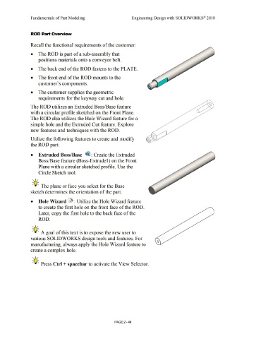
The ROD utilizes an Extruded Boss/Base feature
with a circular profile sketched on the Front Plane.
The ROD also utilizes the Hole Wizard feature for a
simple hole and the Extruded Cut feature. Explore
new features and techniques with the ROD.
Utilize the following features to create and modify
the ROD part:
• Extruded Boss/Base ~ : Create the Extruded
Boss/Base feature (Boss-Extrude 1) on the Front
Plane with a circular sketched profile. Use the
Circle Sketch tool.
, ,/
;Q~ The plane or face you select for the Base
sketch determines the orientation of the part.
• Hole Wizard ~ : Utilize the Hole Wizard feature
to create the first hole on the front face of the ROD.
Later, copy the first hole to the back face of the
ROD.
, ,/
-;Q~ A goal of this text is to expose the new user to
various SOLIDWORKS design tools and features. For
manufacturing, always apply the Hole Wizard feature to
create a complex hole.
, 1 /
;Q~ Press Ctrl + spacebar to activate the View Selector.
PAGE 2 - 46