
Page 121 - Subyek Computer Aided Design - [David Planchard] Engineering Design with SOLIDWORKS
P. 121
Engineering Design with SOLIDWORKS® 201 8 Fundamentals of Part Modeling
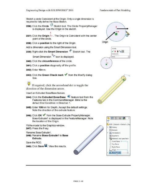
Sketch a circle Coincident at the Origin. Only a single dimension is
required to fully define the Base Sketch.
236) Click the Circle 0 Sketch tool. The Circle PropertyManager
is displayed. Use the Origin in the sketch.
--
237) Click the Origin L . The Origin is Coincident with the center
point of the circle.
Origin
238) Click a position to the right of the Origin.
Add a dimension using the Smart Dimension tool.
Modify
239) Right-click the Smart Dimension <' Sketch tool. The ./ x • ti~~
01@$ketchL
r ,1011 f
Smart Dimension ~(' icon is displayed. 1ol,,m •
•
240) Click the circumference of the circle.
241) Click a position diagonally off the profile.
242) Enter 10mm.
243) Click the Green Check mark ~ from the Modify dialog ~ .. ,. ' lQ
box.
,,,,
-;Q-;, If required, click the arrowhead dot to toggle the
direction of the dimension arrow.
Insert an Extruded Boss/Base feature.
244) Click the Extruded Boss/Base ~ feature tool from the
Features tab in the CommandManager. Blind is the
default End Condition in Direction 1.
245) Enter 100mm for Depth. Accept the default settings.
Note the direction of the extrude feature.
246) Click OK ~ from the Boss-Extrude PropertyManager.
~
Boss-Extrude1 is displayed in the FeatureManager. Note ~ ~ $ ~ >
the location of the Origin. ~
~ ROD (Default< <Default> _Dis
Fit the model to the Graphics window.
247) Press the f key. • 1191 History
la] Sensors
Rename Boss-Extrude1. • IA] Annotations
248) Rename Boss-Extrude1 to Base ~ Equations
o-
Extrude. ~:ii) Material <not specified>
dJ Front Plane ,
Save the ROD.
dJ Top Plane
249) Click Save Ii. View the results. ctJ Right Plane
L. Origin
• ~ Base ~ rude -------
'
PAGE2 - 49