
Page 124 - Subyek Computer Aided Design - [David Planchard] Engineering Design with SOLIDWORKS
P. 124
Fundamentals of Part Modeling Engineering Design with SOLIDWORKS 2018
I Activity: ROD Part - Chamfer Feature
Insert an Angle distance Chamfer feature.
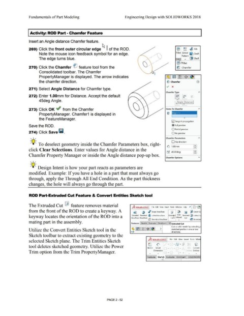
269) Click the front outer circular edge ~ I of the ROD. (B I> c, ~ Rib
c, c,
Note the mouse icon feedback symbol for an edge. .· . ' Fillet Linear ~ Draft
....··· .. ,
.. ·
•• • •••• t \ \ ' ' Pattern [SJ
1
' .
.. -··
The edge turns blue. . . . .·· ... .. · ... ... Shell
. . ..,.
.•. . . . . .... ·.. . .. (E : r-illet
..
270) Click the Chamfer ei feature tool from the .· (ti Chamfer
.
Consolidated toolbar. The Chamfer
PropertyManager is displayed. The arrow indicates ~ ~ ~ $ ~ l
the chamfer direction. ~ Chamfer (1)
v x
271) Select Angle Distance for Chamfer type. ..
,· -
.... ·. ' ·
. . ' " \ ' Chamfer Type
,,. •
I
272) Enter 1.00mm for Distance. Accept the default . . . . \ . ' .
'
.
•
•
'
,.,,
45deg Angle. •• .··
.· , Angle Distance
273) Click OK ~ from the Chamfer .• Items To Chamfer
PropertyManager. Chamfer1 is displayed in
the FeatureManager.
[21 Tangent propagation
Save the ROD. @ Full preview
274) Click Save l"I. O Partial preview
0No preview
Chamfer Parameters
' I ,,
D Flip direction
-,,Q~ To deselect geometry inside the Chamfer Parameters box, right-
(6' 11.oomm
click Clear Selections. Enter values for Angle distance in the
ti [45.00deg
Chamfer Property Manager or inside the Angle distance pop-up box.
Chamfer Options v
' I /
-,,Q~ Design Intent is how your part reacts as parameters are
modified. Example: If you have a hole in a part that must always go
through, apply the Through All End Condition. As the part thickness
changes, the hole will always go through the part.
ROD Part-Extruded Cut Feature & Convert Entities Sketch tool
The Extruded Cut ~ feature removes material 7. ; D .~\."
JjS SOLIDWORKS File Edit View Insert Tools Window Help
1-.
from the front of the ROD to create a keyway. A dfl ~ J'> Swept Boss/Base fJ ~ ~ ~ Swept Cu
Hole Revolved GjD Lofted Ct
Extruded Revolved 6 Lofted Boss/Base
keyway locates the orientation of the ROD into a Boss/Base Boss/Base ~ Extru~ Wizard Cut ~
Cu
Boundary Boss/Base • Boundal')
mating part in the assembly. Features Sketch Evaluate DimXpert SO Extruded Cut
• Cuts a solid model by extruding ,
Utilize the Convert Entities Sketch tool in the ~ 1~ :·~-~$1~] > sketched profile in one or two
~ directions.
Sketch toolbar to extract existing geometry to the
selected Sketch plane. The Trim Entities Sketch J ls SOLIDWORKS File Edit View Insert Tools Wind
~ A • • N . d"i IYl
v
'
L_
tool deletes sketched geometry. Utilize the Power Sketch Smart • • • t.;,·· Tr, Convert
Trim option from the Trim PropertyManager. Dimension fntrt ,r Entities
Features Ske h Evaluate DimXpert SOLIDWORK
•
PAGE2 - 52