Page 125 - Subyek Computer Aided Design - [David Planchard] Engineering Design with SOLIDWORKS
P. 125

Engineering Design with SOLIDWORKS® 2018                                                                                                                                                               Fundamentals of Part Modeling


                                                                       I Activity: ROD Part-Extruded Cut Feature and Convert Entities Sketch tool


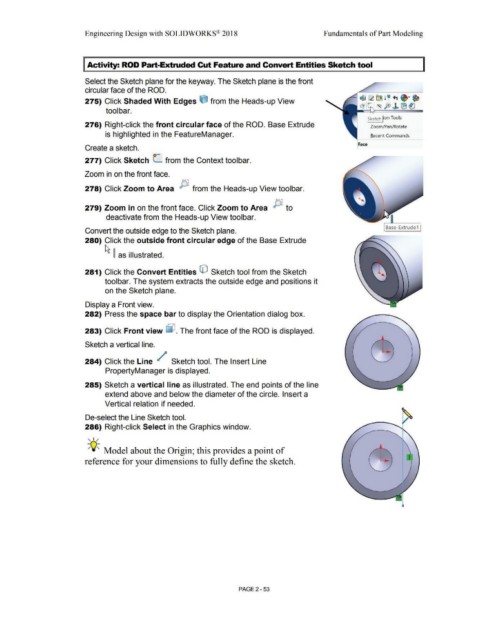
                                                                        Select the Sketch plane for the keyway. The Sketch plane is the front


                                                                        circular face of the ROD.


                                                                                                                                                                                                                                                                                                   ~ t$ @J 9  l ~ ., .T ~
                                                                        275) Click Shaded With Edges e from the Heads-up View                                                                                                                                                                                ~~ '~  fe) ~  (B ~


                                                                                         tool bar.


                                                                                                                                                                                                                                                                                                                  I Sketch lion Tools
                                                                        276) Right-click the front circular face of the ROD.  Base Extrude                                                                                                                                                                            Zoom/Pan/Rotate


                                                                                        is highlighted in the FeatureManager.                                                                                                                                                                                         Recent Commands


                                                                                                                                                                                                                                                                                                            Face
                                                                        Create a sketch.


                                                                        277) Click Sketch L  from the Context toolbar.


                                                                        Zoom in on the front face.


                                                                        278) Click Zoom to Area  µ  from the Heads-up View toolbar.


                                                                                                                                                                                                                                       Ir='.,

                                                                        279) Zoom in on the front face. Click Zoom to Area  P  to


                                                                                         deactivate from the Heads-up View toolbar.


                                                                                                                                                                                                                                                                                                                                   Base-Extrude1
                                                                        Convert the outside edge to the Sketch plane.


                                                                        280) Click the outside front circular edge of the Base Extrude


                                                                                        ~ ~  as illustrated.


                                                                        281) Click the Convert Entities G)  Sketch tool from the Sketch


                                                                                        toolbar. The system extracts the outside edge and positions it


                                                                                        on the Sketch plane.


                                                                        Display a Front view.


                                                                        282) Press the space bar to display the Orientation dialog box.


                                                                        283) Click Front view ~ . The front face of the ROD is displayed.


                                                                        Sketch a vertical line.


                                                                        284) Click the Line  /                                                  Sketch tool. The Insert Line


                                                                                        PropertyManager is displayed.


                                                                        285) Sketch a vertical line as illustrated. The end points of the line


                                                                                        extend above and below the diameter of the circle. Insert a


                                                                                        Vertical relation if needed.


                                                                        De-select the Line Sketch tool.


                                                                        286) Right-click Select in the Graphics window.


                                                                          , ,/


                                                                          -;Q~ Model about the Origin; this provides a point of


                                                                        reference for your dimensions to fully define the sketch.


                                                                                                                                                                                                        PAGE 2 - 53
   120   121   122   123   124   125   126   127   128   129   130