
Page 126 - Subyek Computer Aided Design - [David Planchard] Engineering Design with SOLIDWORKS
P. 126
Fundamentals of Part Modeling Engineering Design with SOLIDWORKS 2018
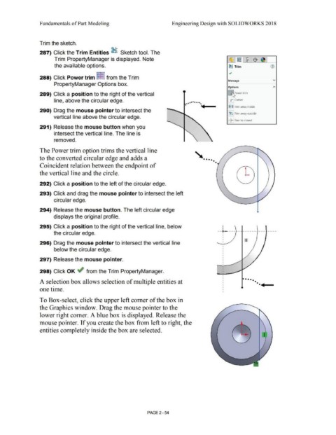
Trim the sketch.
287) Click the Trim Entities ~ Sketch tool. The
Trim PropertyManager is displayed. Note ·~1~ 1~·:$ 1~ 1
the available options. ~ Trim G)
•
288) Click Power trim ::f= from the Trim
Message v
PropertyManager Options box.
Options
289) Click a position to the right of the vertical !ftower trim
. .. ... __
line, above the circular edge. [i Corner
••••••••
•
•
[$ ~!Trim away inside
290) Drag the mouse pointer to intersect the
J:$:j.: Trim away outside
vertical line above the circular edge.
I· ~: Trim to closest
291) Release the mouse button when you
intersect the vertical line. The line is
removed.
The Power trim option trims the vertical line
to the converted circular edge and adds a ' ••••
•
Coincident relation between the endpoint of •
the vertical line and the circle.
292) Click a position to the left of the circular edge.
293) Click and drag the mouse pointer to intersect the left
circular edge.
294) Release the mouse button. The left circular edge
displays the original profile.
295) Click a position to the right of the vertical line, below --i----- ------- --- ----
the circular edge.
'
I
I
I
296) Drag the mouse pointer to intersect the vertical line I
below the circular edge.
297) Release the mouse pointer.
298) Click OK ~ from the Trim PropertyManager.
.. ..
• •••
A selection box allows selection of multiple entities at ••
one time.
To Box-select, click the upper left comer of the box in
the Graphics window. Drag the mouse pointer to the
lower right comer. A blue box is displayed. Release the
mouse pointer. If you create the box from left to right, the
entities completely inside the box are selected.
I
PAGE2 - 54