
Page 119 - Subyek Computer Aided Design - [David Planchard] Engineering Design with SOLIDWORKS
P. 119
Engineering Design with SOLIDWORKS® 201 8 Fundamentals of Part Modeling
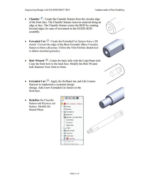
• Chamfer ~ : Create the Chamfer feature from the circular edge
of the front face. The Chamfer feature removes material along an
edge or face. The Chamfer feature assists the ROD by creating
beveled edges for ease of movement in the GUIDE-ROD
assembly.
• Extruded Cut [&] : Create the Extruded Cut feature from a 2D
sketch. Convert the edge of the Boss-Extrude 1 (Base Extrude)
feature to form a Keyway. Utilize the Trim Entities sketch tool
to delete sketched geometry.
• Hole Wizard ~ : Create the back hole with the Copy/Paste tool.
Copy the front hole to the back face. Modify the Hole Wizard
hole diameter from 3mm to 4mm.
• Extruded Cut !&! : Apply the Rollback bar and Edit Feature
function to implement a customer design
change. Add a new Extruded Cut feature to the
front face.
~1~:~1$ :~1 >
• Redefine the Chamfer ~
feature and Keyway cut ~ 0 ROD (Default<<Default>_
feature. Modify the • ~] History
Sketch Plane. ~ Sensors
• IAJ Annotations
[fJ Equations
o-
i::a Material <not specified>
(P Front Plane
(P Top Plane
(P Right Plane
L Origin
• ~ Base Extrude
• ~ Front Cut
• ~ Front Hole
fl O Chamfer1
• :J Keyway Cut
• J 04.0 (4) Back Hole
PAGE 2 -47