
Page 116 - Subyek Computer Aided Design - [David Planchard] Engineering Design with SOLIDWORKS
P. 116
Fundamentals of Part Modeling Engineering Design with SOLIDWORKS® 2018
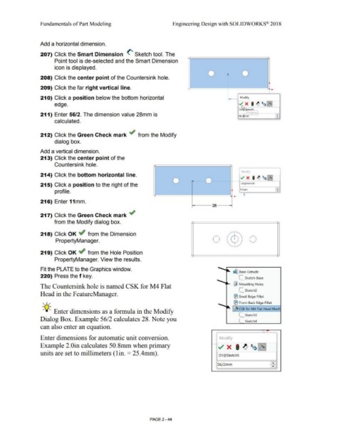
Add a horizontal dimension.
207) Click the Smart Dimension (' Sketch tool. The
Point tool is de-selected and the Smart Dimension
icon is displayed.
0 0
208) Click the center point of the Countersink hole.
209) Click the far right vertical line. tt=====================::::l:i--
21 O) Click a position below the bottom horizontal Modify
edge. ../ X I ~ t..i~ ~.
·~
D~SkerchS
I J1~tan,._e '
211) Enter 56/2. The dimension value 28mm is - •
56/,tTim
•
calculated.
212) Click the Green Check mark if from the Modify
dialog box.
Add a vertical dimension.
213) Click the center point of the
Countersink hole.
Modify
214) Click the bottom horizontal line. yf X I ~ !w~
0 0 ~
215) Click a position to the right of the D2@Sketch5
•
11mm
profile. ' •
tt:=========::::t::==========~· t
216) Enter 11mm.
- -- 28 - -
217) Click the Green Check mark ~
from the Modify dialog box.
218) Click OK ~ from the Dimension
PropertyManager. 0 I ) 0
219) Click OK ~ from the Hole Position
PropertyManager. View the results.
Fit the PLATE to the Graphics window.
~ Base- Extrude
220) Press the f key.
L Sketch-Base
The Countersink hole is named CSK for M4 Flat ~ Mounting Holes
L_ Sketch2
Head in the FeatureManager.
® Small Edge Fillet
, 1 / ® Front-Back Edge Fillet
-;Q~ Enter dimensions as a formula in the Modify "' ~ CSK for M4 Flat Head Mach
L_ Sketch3
Dialog Box. Example 56/2 calculates 28. Note you
Sketch4
can also enter an equation.
Enter dimensions for automatic unit conversion. Modify
Example 2.0in calculates 50.Smm when primary ~ ../ x I ~ tg~ ~
uni ts are set to millimeters ( 1 in. = 25. 4 mm). D1 @Sketch5
56/2mm
PAGE 2 - 44