
Page 112 - Subyek Computer Aided Design - [David Planchard] Engineering Design with SOLIDWORKS
P. 112
Fundamentals of Part Modeling Engineering Design with SOLIDWORKS® 2018
Fit the PLATE to the Graphics window.
164) Press the f key.
Save the PLATE.
165) Click Save 111. View the results.
, 1,,
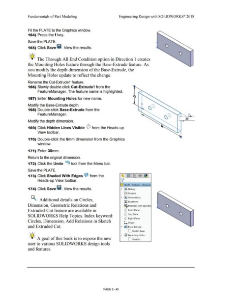
-;Q~ The Through All End Condition option in Direction 1 creates
the Mounting Holes feature through the Base-Extrude feature. As
you modify the depth dimension of the Base-Extrude, the
Mounting Holes update to reflect the change.
Rename the Cut-Extrude1 feature.
166) Slowly double click Cut-Extrude1 from the
FeatureManager. The feature name is highlighted.
167) Enter Mounting Holes for new name.
Modify the Base-Extrude depth.
168) Double-click Base-Extrude from the
FeatureManager. ' ........... /
30
Modify the depth dimension.
169) Click Hidden Lines Visible ® from the Heads-up
View toolbar.
170) Double-click the 5mm dimension from the Graphics
window.
171) Enter 30mm.
Return to the original dimension.
172) Click the Undo ts) tool from the Menu bar.
Save the PLATE.
173) Click Shaded With Edges e from the ~,~.~1$ .~I
Heads-up View toolbar. v
~ PLATE (Default<<Default
174) Click Save lii. View the results. • [€> I History
Ca] Sensors
• IA] Annotations
~ Additional details on Circles,
ll:J Equations
o-
Dimension, Geometric Relations and ;=c; Material <not specifie
Extruded-Cut feature are available in Q Front Plane
SOLIDWORKS Help Topics. Index keyword: Q Top Plane
Q Right Plane
Circles, Dimension, Add Relations in Sketch
l.. Origin
and Extruded Cut. • ~ Base-Extrude
, 1,, L Sketch-Base
... ~ Mounting Holes
-;Q~ A goal of this book is to expose the new C Sketch2
user to various SOLIDWORKS design tools
and features.
PAGE 2 - 40