
Page 107 - Subyek Computer Aided Design - [David Planchard] Engineering Design with SOLIDWORKS
P. 107
Engineering Design with SOLIDWORKS® 2018 Fundamentals of Part Modeling
PLATE Part- Extruded Cut Feature
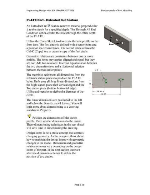
An Extruded Cut ~ feature removes material perpendicular
1- to the sketch for a specified depth. The Through All End
Condition option creates the holes through the entire depth
of the PLATE.
Utilize the Circle Sketch tool to create the hole profile on the
front face. The first circle is defined with a center point and
a point on its circumference. The second circle utilizes the
Ctrl-C (Copy) key to create a copy of the first circle.
Geometric relations are constraints between one or more
entities. The holes may appear aligned and equal, but they
are not! Add two relations: Insert an Equal relation between
the two circumferences and a Horizontal relation
between the two center points. <t>4
\
The machinist references all dimensions from the
reference datum planes to produce the PLATE L
' + .... 4 .~Qifl
¥
holes. Reference all three linear dimensions from • - ~
1 1
the Right datum plane (left vertical edge) and the I
Top datum plane (bottom horizontal edge). '
Utilize a dimension to define the diameter of the 16.50 --
circle. 39.50
The linear dimensions are positioned to the left
and below the Boss-Extrude 1 feature. You will
learn more about dimensioning to a drawing
standard in Project 3.
, 1 /
-;Q~ Position the dimensions off the sketch
profile. Place smaller dimensions to the inside.
These dimensioning techniques in the part sketch
will save time in dimensioning the drawing.
Design intent is not a static concept that controls
changing geometry. As the designer, think about
how to maintain the design intent with geometric
changes to the model. Dimension and geometric
relation schemes vary depending on the design
intent of the part. In the next section there are
alternate dimension schemes to define the
position of two circles.
PAGE2 -35