
Page 106 - Subyek Computer Aided Design - [David Planchard] Engineering Design with SOLIDWORKS
P. 106
Fundamentals of Part Modeling Engineering Design with SOLIDWORKS® 2018
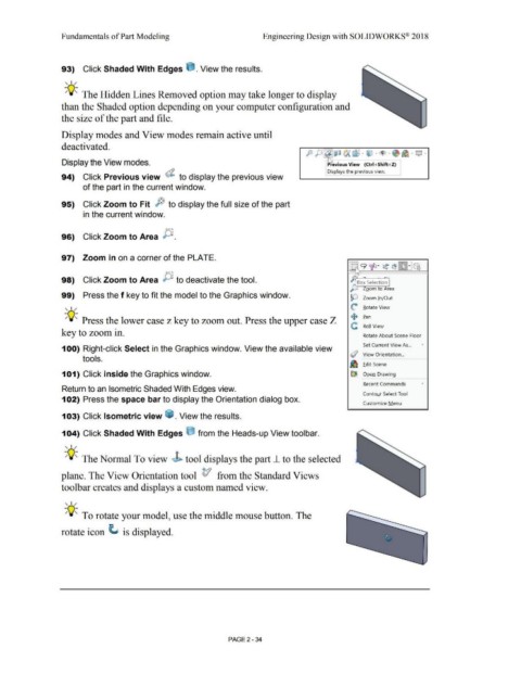
93) Click Shaded With Edges ~ . View the results.
, 1 /
-;Q~ The Hidden Lines Removed option may take longer to display
than the Shaded option depending on your computer configuration and
the size of the part and file.
Display modes and View modes remain active until
deactivated.
p J)J~i) (A (:j . iJ . ~ .• ~ . Q •
Display the View modes. ~evious View {Ctrl+Shift+Z}
I Displays the previous view. .
94) Click Previous view (i. to display the previous view
of the part in the current window.
95) Click Zoom to Fit ;~ to display the full size of the part
in the current window.
96) Click Zoom to Area P .
97) Zoom in on a corner of the PLATE.
98) Click Zoom to Area JJ to deactivate the tool. ~Box Selectio~
J ,: Loom to Area
99) Press the f key to fit the model to the Graphics window.
!Q Zoom l n/Out
, 1 / ({: Rotate View
-;Q~ Press the lower case z key to zoom out. Press the upper case Z + Ean
C Roll View
key to zoom in. Rotate About Scene Floor
Set Current View As... •
100) Right-click Select in the Graphics window. View the available view
(/ "i,jew Orientation ...
tools.
iiD Edit Scene
101) Click inside the Graphics window. ~ Open Drawing
Recent Commands •
Return to an Isometric Shaded With Edges view.
Contour Select Tool
102) Press the space bar to display the Orientation dialog box.
Customize Menu
103) Click Isometric view ~ . View the results.
104) Click Shaded With Edges e from the Heads-up View tool bar.
, 1 /
-;Q~ The Normal To view J> tool displays the part 1- to the selected
plane. The View Orientation tool t1 from the Standard Views
toolbar creates and displays a custom named view.
, 1 /
-;Q~ To rotate your model, use the middle mouse button. The
rotate icon ~ is displayed.
PAGE2 - 34