Page 111 - Subyek Computer Aided Design - [David Planchard] Engineering Design with SOLIDWORKS
P. 111

Engineering Design with SOLIDWORKS® 2018                                                                                                                                                               Fundamentals of Part Modeling


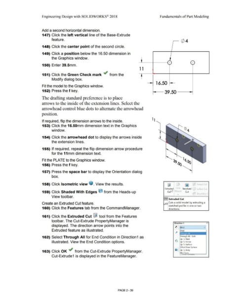
                                                                       Add a second horizontal dimension.


                                                                        147) Click the left vertical line of the Base-Extrude


                                                                                        feature.


                                                                        148) Click the center point of the second circle.


                                                                        149) Click a position below the 16.50 dimension in


                                                                                        the Graphics window.
                                                                                                                                                                                                                                                                                             --                                      -

                                                                                                                                                                                                                                            --'---+----+-:  + )                                                                    (  +  )
                                                                        150) Enter 39.Smm.                                                                                                                                                                                                    --


                                                                                                                                                                                                                                             1 1


                                                                        151) Click the Green Check mark ~ from the                                                                                                                             t


                                                                                        Modify dialog box.


                                                                                                                                                                                                                                                                        16.50  ~

                                                                        Fit the model to the Graphics window.


                                                                        152) Press the f key.                                                                                                                                                                      i---- 39 .50 -                                         ~


                                                                        The drafting standard preference is to place


                                                                        arrows to the inside of the extension lines. Select the


                                                                        arrowhead control blue dots to alternate the arrowhead


                                                                       position.


                                                                        If required, flip the dimension arrows to the inside.


                                                                        153) Click the 16.SOmm dimension text in the Graphics


                                                                                        window.


                                                                        154) Click the arrowhead dot to display the arrows inside


                                                                                        the extension lines.


                                                                        155) If required,  repeat the flip dimension arrow procedure


                                                                                        for the 11 mm dimension text.


                                                                        Fit the PLATE to the Graphics window.


                                                                        156) Press the f key.


                                                                        157) Press the space bar to display the Orientation dialog


                                                                                        box.


                                                                        158) Click Isometric view ~ . View the results.                                                                                                                                                                     @]                            ~                   Swept Cut


                                                                                                                                                                                                                                                                                       ExtrucM._d  1-iole  Revolved                           Lofted Cut

                                                                        159) Click Shaded With Edges t:l from the Heads-up                                                                                                                                                                  Curs'"  W1za•d                Cut

                                                                                                                                                                                                                                                                                                             ...                              Boundary C
                                                                                        View toolbar.

                                                                                                                                                                                                                                                                                      OLI  Extruded Cut


                                                                        Create an Extruded Cut feature.                                                                                                                                                                                AT  Cuts a solid model by extruding a

                                                                                                                                                                                                                                                                                              sketched profile in one or two
                                                                        160) Click the Features tab from the CommandManager.                                                                                                                                                                  directions.


                                                                        161) Click the Extruded Cut I&!  tool from the Features


                                                                                        toolbar. The Cut-Extrude PropertyManager is

                                                                                                                                                                                                                                                                                                       Direction 1
                                                                                        displayed. The direction arrow points into the

                                                                                                                                                                                                                                                                                                       ~ f--Bli_nd _____ v
                                                                                        Extruded feature as illustrated.                                                                                                                                                                                         Blind


                                                                        162) Select Through All for End Condition in Direction1  as                                                                                                                                                                              Thro

                                                                                                                                                                                                                                                                                                                 Up To Next
                                                                                        illustrated. View the End Condition options.                                                                                                                                                                     G  Up To Vertex


                                                                                                                                                                                                                                                                                                                 Up To Surface

                                                                                                                                                                                                                                                                                                       ~ Offset From Surface

                                                                        163) Click OK ~ from the Cut-Extrude PropertyManager.                                                                                                                                                                          ~ UpToBody
                                                                                                                                                                                                                                                                                                                 Mid Plane

                                                                                        Cut-Extrude1  is displayed in the FeatureManager.


                                                                                                                                                                                                        PAGE2 - 39
   106   107   108   109   110   111   112   113   114   115   116