
Page 110 - Subyek Computer Aided Design - [David Planchard] Engineering Design with SOLIDWORKS
P. 110
Fundamentals of Part Modeling Engineering Design with SOLIDWORKS® 2018
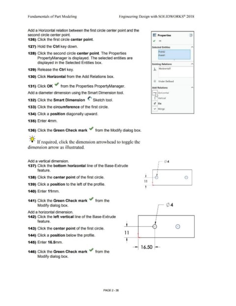
Add a Horizontal relation between the first circle center point and the
second circle center point. ~ Properties (1)
126) Click the first circle center point. .; ......
127) Hold the Ctrl key down. Selected Entities A
Point2
128) Click the second circle center point. The Properties
Point4
PropertyManager is displayed. The selected entities are
•
displayed in the Selected Entities box.
Existing Relations A
129) Release the Ctrl key. ..b.. Horizontal 1
130) Click Horizontal from the Add Relations box.
CD Under Defined
131) Click OK ~ from the Properties PropertyManager.
Add Relations A
Add a diameter dimension using the Smart Dimension tool. - r-s Horizontal
-
>
I LI\ Vertical
132) Click the Smart Dimension (' Sketch tool.
~ fix
133) Click the circumference of the first circle.
V' Merge
134) Click a position diagonally upward.
135) Enter 4mm.
136) Click the Green Check mark ~ from the Modify dialog box.
, ,/
-;Q~ If required, click the dimension arrowhead to toggle the
dimension arrow as illustrated.
Add a vertical dimension.
137) Click the bottom horizontal line of the Base-Extrude
feature.
138) Click the center point of the first circle. + 8
1 1
139) Click a position to the left of the profile. "
t
140) Enter 11mm.
141) Click the Green Check mark ~ from the
Modify dialog box.
Add a horizontal dimension.
142) Click the left vertical line of the Base-Extrude
feature.
.....
'+ ) 0
143) Click the center point of the first circle. ' --
1 1
144) Click a position below the profile.
'
t
145) Enter 16.Smm.
16.50
146) Click the Green Check mark ~ from the
Modify dialog box.
PAGE 2-38