
Page 108 - Subyek Computer Aided Design - [David Planchard] Engineering Design with SOLIDWORKS
P. 108
Fundamentals of Part Modeling Engineering Design with SOLIDWORKS® 2018
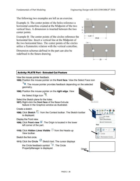
The following two examples are left as an exercise. 0 4 ,
Example A: The center points of the holes reference a
horizontal centerline created at the Midpoint of the two • ] -
• I •
--
vertical lines. A dimension is inserted between the two
1 1
center points.
'
Example B: The center points of the circles reference the 16.50-
39.50
horizontal line. Insert a vertical line at the Midpoint of
the two horizontal lines. The center points of the circles Q'> 4 \
\
utilize a Symmetric relation with the vertical centerline.
l - -
Dimension schemes defined in the part can also be I J J
--
redefined in the future drawing.
23--+
I Activity: PLATE Part - Extruded Cut Feature
View the mouse pointer feedback.
105) Position the mouse pointer on the front face. View the Select Face icon
~
~ . The mouse pointer provides feedback depending on the selected
geometry.
106) Position the mouse pointer on the right edge. View
the Select Edge icon ~~ .
Select the Sketch plane for the holes.
107) Right-click the front face of the Base-Extrude
feature in the Graphics window as illustrated.
Create a sketch.
108) Click Sketch C from the Context tool bar. The Sketch tool bar
is displayed.
J Sketch Jon Tools
Display the Front view. Zoom/Pan/ Rotate
109) Click Front view lJ?. The Origin is located in the lower R ecent Commands
left corner of the part. Face
,.
•
11 O) Click Hidden Lines Visible ® from the Heads-up 0 " N " .
• •
••
View toolbar. c Circle
Sketch the first circle. O Perimeter Circle
111) Click the Circle 0 Sketch tool. The cursor displays
I
I
the Circle feedback symbol 0 . The Circle
PropertyManager is displayed.
Ori~
*-"" _______ ____.
PAGE2-36