
Page 103 - Subyek Computer Aided Design - [David Planchard] Engineering Design with SOLIDWORKS
P. 103
Engineering Design with SOLIDWORKS® 2018 Fundamentals of Part Modeling
In edit mode, right-click anywhere on an extruded feature and modify the Direction 1
G Reverse Direction
end condition from a pop-up shortcut menu. Click in empty space, on
G Blind
geometry, or on the handle. The pop-up shortcut menu provides the
Up To Vertex
document dependent options for Direction 1 and Direction 2. Up To Surface
, ,/ Offset From Surface
Up To Body
-;Q~ Display an Isometric view of the model. Press the space bar to
Mid Plane
display the Orientation dialog box. Click the Isometric view ~ icon. Direction 2
G Direction 2 Off
Blind
Up To Vertex
Up To Surface
Offset From Surface
Up To Body
PLATE Part - Modify Dimensions and Rename -- y
Incorporate a design change into the PLATE. Modify / Modify
dimension values in the Modify dialog box or directly in the ., x I~~ ~
Graphics window. Utilize the Rebuild I tool to update the 01 @Boss-Extrude1
Extruded Boss/Base feature. 10.00mm ...
•
Either double-click the Boss-Extrude 1 folder from the
F eatureManager or double-click on the feature in the Graphics window to display the
model dimensions. Rename entries by selecting on the text (slowly double-click) in the
F eatureManager.
Activity: PLATE Part- Modify Dimensions and Rename
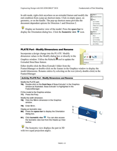
Modify the PLATE part.
76) Double-click on the front face of Boss-Extrude1 in the Graphics
window as illustrated. Boss-Extrude1 is highlighted in the
FeatureManager.
Fit the model to the Graphics window.
77) Press the f key.
Modify the width dimension.
78) Click the 1 Omm dimension in the Graphics
window.
79) Enter 5mm.
Display an Isometric view.
80) Press the space bar to display the Orientation
dialog box.
81) Click Isometric view ~ . You can also access
the Isometric view tool from the Heads-up View
tool bar.
, ,/
-;Q~ The Isometric view displays the part in 30
with two equal projection angles.
PAGE2 -31