Page 100 - Subyek Computer Aided Design - [David Planchard] Engineering Design with SOLIDWORKS
P. 100

Fundamentals of Part Modeling                                                                                                                              Engineering Design with SOLIDWORKS® 2018


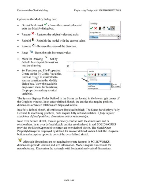
                                                Options in the Modify dialog box:


                                                                                                                                                                                                                                                        Modify
                                                •           Green Check mark ../ - Saves the current value and


                                                            exits the Modify dialog box.                                                                                                                                                             ~ x                      ,~                    ~~~


                                                                                                                                                                                                                                                       D2@Sketc               h1
                                                •           Restore X  - Restores the original value and exits.                                                                                                                                                                Distance (Enter a valu~


                                                                                                                                                                                                                                                     e2.oomm                                                                      -

                                                                                                                                                                                                                                                                                                                                  •

                                                •           Rebuild I  -Rebuilds the model with the current value .


                                                •           Reverse  ~ - Reverse the sense of the direction .


                                                                                 +

                                                •           Reset  IJ~  - Reset the spin increment value .


                                                •  Mark for Drawing                                                         '.::i    - Set by


                                                            default. Inserts part dimensions                                                                                              f


                                                            into the drawing.                                                                                                          22


                                                •  Set Functions and File Properties.                                                                                                                    ..                                        Modify


                                                            Create on the fly Global Variables.                                                                                                                                                  ~                         ~       ~~~
                                                                                                                                                                                                                                                           x
                                                                                                                                                                                                                                      56 -                        I
                                                            Enter an =  sign as illustrated to


                                                            start an equation in the Modify


                                                            dialog box. View the available                                                                                                                                                                                                                     ~ a (30)


                                                            drop-down menu for functions,                                                                                                                                                         Fune  ions                                                >  ~ b (22mm)


                                                                                                                                                                                                                                                  File Properties                                           >
                                                            file properties and any created


                                                            variables.


                                                The System displays Under Defined in the Status bar located in the lower right comer of


                                                the Graphics window. In an under defined Sketch, the entities that require position,


                                                dimensions or Sketch relations are displayed in blue.


                                                In a fully defined sketch, all entities are displayed in black. The Status bar displays Fully


                                                Defined. In machining practices, parts require fully defined sketches. A fully defined


                                                sketch has defined positions, dimensions and/or relationships.


                                                In an over defined sketch, there is geometry conflict with the dimensions and or


                                                relationships. In an over defined sketch, entities are displayed in red. SOLIDWORKS


                                                provides the SketchXpert tool to correct an over defined sketch. The SketchXpert


                                                PropertyManager is displayed by default for an over defined sketch. Click the Diagnose


                                                button and accept an option to correct the over defined sketch.


                                                   , ,/


                                                  ;Q~ Although dimensions are not required to create features in SOLIDWORKS,


                                                dimensions provide location and size information. Models require dimensions for


                                                manufacturing.  Dimension the rectangle with horizontal and vertical dimensions.


                                                                                                                                                                                PAGE2 - 28
   95   96   97   98   99   100   101   102   103   104   105