
Page 99 - Subyek Computer Aided Design - [David Planchard] Engineering Design with SOLIDWORKS
P. 99
Engineering Design with SOLIDWORKS® 2018 Fundamentals of Part Modeling
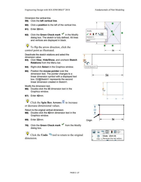
Dimension the vertical line.
59) Click the left vertical line.
\
60) Click a position to the left of the vertical line. • \ '
\
61) Enter 22mm. \ •
'
Modify
~ x • .I' 1~~~
62) Click the Green Check mark ~ in the Modify
'
dialog box. The sketch is fully defined. All lines 02 iSketcb I
Distance . '
I
and vertices are displayed in black. 22lmm ~ •
'
, 1 /
-;Q~ To flip the arrow direction, click the
control point as illustrated.
Deactivate the sketch relations and select the
dimension value.
- -
63) Click View, Hide/Show, and uncheck Sketch ~
", I
Relations from the Menu bar. ~~('
64) Right-click Select in the Graphics window. - D2@Sketch1
65) Position the mouse pointer over the
dimension text. The pointer changes to a
56
linear dimension symbol with a displayed text
box. D2@Sketch 1 represents the second
linear dimension created in Sketch1.
Modify the dimension text.
66) Double-click the 22 dimension text in the
Graphics window.
67) Enter 42mm.
- 56 -
, 1 /
-;Q~ Click the Spin Box Arrows ~ to increase
or decrease dimensional values.
Return to the original vertical dimension. 22
68) Double-click the 42mm dimension text in the
Graphics window.
69) Enter 22mm. Origin
70) Click the Green Check mark ~ from the Modify
dialog box.
Ii·~ · ~ I
~
, 1 / ,. ,. rm@·
"'
-;Q~ Click the Undo ~ tool to return to the original
Jt ® Undo (Ctrl+Z)
dimension. Reverses the last action.
Jt Fillet Li '-'1\A I\. 11 1 1."'- 1 .J'-'-'
PAGE 2 - 27