
Page 94 - Subyek Computer Aided Design - [David Planchard] Engineering Design with SOLIDWORKS
P. 94
Fundamentals of Part Modeling Engineering Design with SOLIDWORKS® 2018
Utilize the Heads-up View toolbar or the p j)] (J. ~ (A ~ ~,© · 1J' • ~ ~ • Q •
Orientation dialog box to orient or set view style \) ~® »
for your model. @ @13
@~@C!j
Before incorporating your design intent into the
@ J>
Sketch plane, ask a question: How will the part be
D8LDtE t~
oriented in the assembly? Answer: Orient or align
the part to assist in the final assembly. Utilize the
Front Plane to create the Extruded Base feature
for the PLATE part.
PLATE Part - Extruded Boss/Base Feature
An Extruded Boss/Base ~ feature is a feature in SOLIOWORKS that utilizes a
sketched profile and extends the profile perpendicular (__L) to the Sketch plane.
In SOLIOWORKS, a 20 profile is called a sketch. A sketch requires a Sketch plane and a
20 profile. The sketch in this example uses the Front Plane. The 20 profile is a rectangle.
Geometric relationships and dimensions define the exact size of the rectangle. The
rectangle is extruded perpendicular to the Sketch plane.
The Front Plane's imaginary boundary is represented on the screen with four visible
edges. Planes are flat and infinite. Planes are used as the primary sketch surface for
creating Extruded Boss/Base and Extruded Cut features.
I Activity: PLATE Part - Extruded-Base Feature
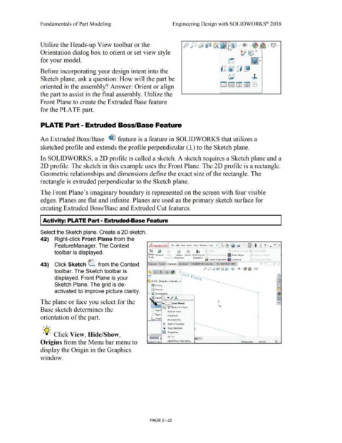
Select the Sketch plane. Create a 20 sketch.
42) Right-click Front Plane from the
FeatureManager. The Context j is SOLJDWORKS file Edit View Insert Toob Window Help it l ·~-lg· &I • • ... • I 3 ? · _ n x
tool bar is displayed. Y.Y ,fJ Q: 0 l, r I y
Design Measure S.,c:tion Sensor Perform.nee r ~ Zebra Slripes
Study
1 Properties Evaluation r::;;.,
• ¥ Import Diagnostics CtJ1vature
1-~~
43) Click Sketch (_ from the Context Features Sketch E11aluat e DimXpert SOUDWORKS Add-ll1s SOUDWORKS MBD .-, n _ c5l X
_ _ _ • .:::, J:1 ~ iJ (A Ci, - I) - 11 • • ~ • Q -
toolbar. The Sketch toolbar is ~ rirnr~ 1 $ ~ > ;---__
displayed. Front Plane is your "1 on t P1<lt)'- ~
'-.::j) ~LA TE (Default< <Default> . Di e --------------- GiJ
Sketch Plane. The grid is de- ~ Hiiilory - ------ t:'.J
activated to improve picture clarity. t1 Sensors ·-------- b~
The plane or face you select for the :.,, ate F~ Ske:W~ront Plane) t ..
k ront l!:io ketch On Plane
Base sketch determines the [:;J Top P Section View
1
l :' Right Comment
f"
orientation of the part.
L. origi
.ea rent/Child ...
Ii) Add to Favorites
, 1 /
~ Sa11e Selection
-;Q~ Click View, Hide/Show, ( jggJ Propertl~ .. -
.Go To .•.
dy 1
Origins from the Menu bar menu to reates a new liide/Show Tree Items ... Editinq Part MMGS · ~
display the Origin in the Graphics
window.
PAGE2 - 22