
Page 93 - Subyek Computer Aided Design - [David Planchard] Engineering Design with SOLIDWORKS
P. 93
Engineering Design with SOLIDWORKS® 201 8 Fundamentals of Part Modeling
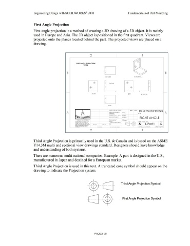
First Angle Projection
First-angle projection is a method of creating a 2D drawing of a 3D object. It is mainly
used in Europe and Asia. The 3D object is positioned in the first quadrant. Views are
projected onto the planes located behind the part. The projected views are placed on a
drawing.
2 l
FIRST ANGLE PROJECTION
VIEWS
..
-~
•
•
. ,
•
•
B •• B
•
•
BOTTOM ISOMETRIC
·$- FRONT
·(±)· ·$·
RIGHT LEFT BOTTOM
TOP
•••. ·~· D&M ENGINEERING
A A
ttM 1.:ow..o.t: o,ueuo THE:
All<)U1.,.l' •AC 11: lhl O: l ll¢NH
l'MO f1A¢l OfCto.t,.., ,
IIUUUA1ll H(-1 ! M • G " '" RIGHT ANGLE
MUIUI Gt Oot«lUI: ••
uo,11n .. u .aH) c.o,mo1w11.a, l OUtAIK"G Ht. .... e-rw
llll M1¢flMN!Otl ¢0111/VltEO ,t0l11f -11- Sf E DWG. NO. REV
(HilWl'!() f lllf $()~ •tO"(~V <)I Piow\ Co,bon Sl••I
INS,(11 C;()l#Al<Y IIAA'( •Jtl)', Altf
H'l'tOOUCIION IN IAtl Ot !>$ AWIIOU A L-Partl A
Wf110..-11,r 11,uuN uuu:uow o, IIUI ~SY
~M!'fll ¢0f#AIN IIAA'C 11(1(> 1$
' SCAlE: 1:2 WEIGHT: SHEET I 01 I
2 l
Third Angle Projection is primarily used in the U.S. & Canada and is based on the ASME
Yl4.3M multi and sectional view drawings standard. Designers should have knowledge
and understanding of both systems.
There are numerous multi-national companies. Example: A part is designed in the U.S.,
manufactured in Japan and destined for a European market.
Third Angle Projection is used in this text. A truncated cone symbol should appear on the
drawing to indicate the Projection system.
I Third Angle Projection Symbol
- ~ - -----
I
-© First Angle Projection Symbol
I
PAGE 2 - 21