
Page 89 - Subyek Computer Aided Design - [David Planchard] Engineering Design with SOLIDWORKS
P. 89
Engineering Design with SOLID\VORKS" 2018 Fundamentals of Part Modeling
Machined Part
In earlier conversations with manufacturing, a
decision was 1nade that the part would be
machined.
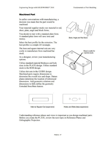
Your material supplier stocks raw material in rod,
sheet, plate, angle and block forms.
You decide to start with a standard plate form.
A standard plate form wi II save time and
Block, Anrje and Rod Stock
money.
Select the best profile for the extrusion. The
best profile is a simple 20 rectangle.
The boss and square internal cuts are very
costly to 1nanufacture from machined bar Boss is costly lo<
machine stock.
stock.
As a designer, review your 111anufacturing
options.
Utilize standard material thickness and hole
sizes in the PLATE design. Utilize standard
stock in the ROD design.
Utilize slot cuts in the GUIDE design.
Machined parts require dimensions to
detem1ine the overall size and shape. Datum
planes determine the location of referenced
dimensions. Add geometric relations and
dimensions to full y define the geometry
Extruded Boss/Base feature.
I I
Internal Square Cut (expensive) Holes and Slots (less expensive)
Understanding reference planes and views is i1nportant as you design machined parts.
Before you create the PLATE, review the next topic on Reference Planes and
Orthographic Projection.
PAGE 2-17