
Page 85 - Subyek Computer Aided Design - [David Planchard] Engineering Design with SOLIDWORKS
P. 85
Engineering Design with SOLIDWORKS® 2018 Fundamentals of Part Modeling
PLATE Part Overview
Determine the functional and geometric
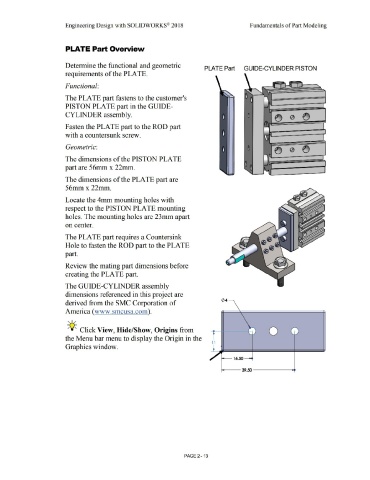
PLATE Part GUIDE-CYLINDER PISTON
requirements of the PLATE.
Functional:
The PLATE part fastens to the customer's
PISTON PLATE part in the GUIDE-
CYLINDER assembly.
Fasten the PLATE part to the ROD part
with a countersunk screw.
Geometric:
The dimensions of the PISTON PLATE
part are 56mm x 22mm.
The dimensions of the PLATE part are
56mmx22mm.
Locate the 4mm mounting holes with
respect to the PISTON PLATE mounting
holes. The mounting holes are 23mm apart
on center.
The PLATE part requires a Countersink
Hole to fasten the ROD part to the PLATE
part.
Review the mating part dimensions before
creating the PLATE part.
The GUIDE-CYLINDER assembly
dimensions referenced in this project are
derived from the SMC Corporation of
America (www.smcusa.com).
, 1 /
-;Q~ Click View, Hide/Show, Origins from 0
the Menu bar menu to display the Origin in the r
11
Graphics window. t
~ 16.50 __.
i------- 39.50 ----------
PAGE 2 - 13