Page 86 - Subyek Computer Aided Design - [David Planchard] Engineering Design with SOLIDWORKS
P. 86

Fundamentals of Part Modeling                                                                                                                              Engineering Design with SOLIDWORKS® 2018


                                                Start the translation of the initial design functional and geometric


                                                requirements into SOLIDWORKS features.


                                                What are features?


                                                •  Features are geometry building blocks.


                                                •  Features can add or remove material.


                                                •  Features are created from sketched profiles or from edges and


                                                            faces of existing geometry.


                                                Utilize the following features to create the PLATE part:


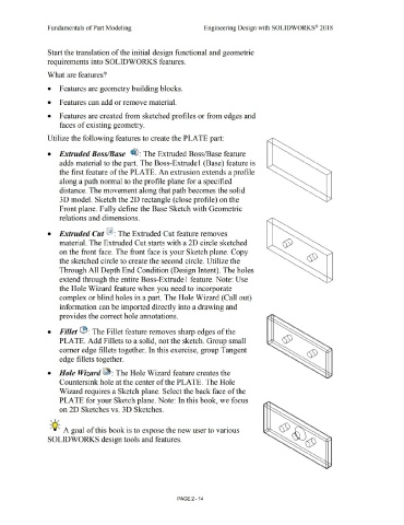
                                                •  Extruded Boss/Base  ~ : The Extruded Boss/Base feature


                                                            adds material to the part. The Boss-Extrude 1 (Base) feature is


                                                            the first feature of the PLATE. An extrusion extends a profile


                                                            along a path normal to the profile plane for a specified


                                                            distance. The movement along that path becomes the solid


                                                            3D model. Sketch the 2D rectangle ( close profile) on the


                                                            Front plane. Fully define the Base Sketch with Geometric


                                                            relations and dimensions.


                                                •  Extruded Cut ~ : The Extruded Cut feature removes


                                                            material. The Extruded Cut starts with a 2D circle sketched


                                                            on the front face. The front face is your Sketch plane. Copy


                                                            the sketched circle to create the second circle. Utilize the


                                                            Through All Depth End Condition (Design Intent). The holes


                                                            extend through the entire Boss-Extrude! feature. Note: Use


                                                            the Hole Wizard feature when you need to incorporate


                                                            complex or blind holes in a part. The Hole Wizard (Call out)


                                                            information can be imported directly into a drawing and


                                                            provides the correct hole annotations.


                                                •  Fillet lB: The Fillet feature removes sharp edges of the


                                                            PLATE. Add Fillets to a solid, not the sketch. Group small


                                                            comer edge fillets together. In this exercise, group Tangent


                                                            edge fillets together.


                                                •  Hole Wizard ~ : The Hole Wizard feature creates the


                                                            Countersink hole at the center of the PLATE. The Hole


                                                            Wizard requires a Sketch plane. Select the back face of the


                                                            PLATE for your Sketch plane. Note: In this book, we focus


                                                            on 2D Sketches vs. 30 Sketches.


                                                   , 1 /


                                                  -;Q~ A goal of this book is to expose the new user to various


                                                SOLIDWORKS design tools and features.


                                                                                                                                                                                PAGE 2 - 14
   81   82   83   84   85   86   87   88   89   90   91