
Page 88 - Subyek Computer Aided Design - [David Planchard] Engineering Design with SOLIDWORKS
P. 88
Fundamentals of Part Modeling Engineering Design with SOLIDWORKS® 2018
PLATE is displayed in the FeatureManager design tree. The ~1~ 1~1$ , >
Part ~ icon is displayed at the top of the FeatureManager. v
l ~ PLATE (Default< <Default> _Di
' I /
-;Q;_ The origin represents the intersection of the Front, Top l@I History
lfrl Sensors
and Right planes.
~ [A I Annotations
, 1 /
[t:I Equations
-;Q;_ Click View, Hide/Show, Origins from the Menu bar menu o-
~=o Material < not specified >
to display the Origin in the Graphics window. dJ Front Plane
dJ Top Plane
dJ Right Plane
L Origin
Base Feature
What is a Base feature? The Base feature (Boss-Extrude 1) is the first feature that is
created. The Base feature is the foundation of the part. Keep the Base feature simple!
The Base feature geometry for the PLATE is an extrusion. Rename the base feature
Extruded-Base. Note: The default name is Boss-Extrude I.
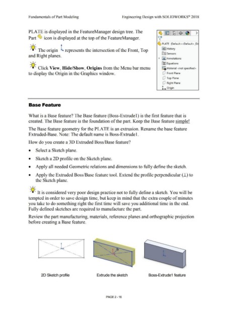
How do you create a 30 Extruded Boss/Base feature?
• Select a Sketch plane.
• Sketch a 2D profile on the Sketch plane.
• Apply all needed Geometric relations and dimensions to fully define the sketch.
• Apply the Extruded Boss/Base feature tool. Extend the profile perpendicular (_i) to
the Sketch plane.
, 1 /
-;Q;. It is considered very poor design practice not to fully define a sketch. You will be
tempted in order to save design time, but keep in mind that the extra couple of minutes
you take to do something right the first time will save you additional time in the end.
Fully defined sketches are required to manufacture the part.
Review the part manufacturing, materials, reference planes and orthographic projection
before creating a Base feature .
• , .,./'
" • , .,./' •
" • , .,./' "
'
" .,./'
, • " t • -
, .,./' " • ->Y~- -
, .,./' " • -- --- "
" '
"
'
"
'
20 Sketch profile Extrude the sketch Boss-Extrude1 feature
PAGE2 - 16