
Page 91 - Subyek Computer Aided Design - [David Planchard] Engineering Design with SOLIDWORKS
P. 91
Engineering Design with SOLID\VORKS" 2018 Fundamentals of Part Modeling
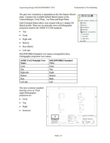
The part view orientation is dependent on the first feature Sketch
~ l!rn.re,.-$.~ j >
plane. Compare the available defaL Llt Sketch planes in the
FeatureManager: Front Plane, Top Plane and Right Plane. 'fl
C, PLAlE (O~fauft,;<D~fauh;,,_Oi:
Each Extruded feature above was created with an L-shaped 20 l'.&)HU1oty
Sketch profile. There are six principle views of Orthographic ~ S,nwr;
projection listed in the ASME Y I 4.3M standards: • {&) Annotations
·-
00 Equations
• Top !:O Mateetial .;not spe·dfied,
Cl F-ront Pinn•
• Front CJ lop Pl~.ne
• Right side c;J Alght Plane
L o,, tn
9
• Botton,
• Rear (Back)
• Left side
SOLlDWORKS Standard view names correspond to these
Orthographic projection view aan1es.
ASME Yl4.3 Principle View SOLID\VORKS Standard
Name: View:
Front Front
Top Too
Ri<>ht side Ri'1ht
Bottom Bottom
Rear Back
Left side Left
The most common standard 2
drawing views in Third
angle Orthographic
projection are: D
e e
• Front
• Top
• Right L
• Isometric ...,.. ~·-·
__ , .... -
--·
A ·-·
.... -.... -. --
:.'!!':;:;';'~":'" ,.._,
RIGI-IT ANGLE
---·-
.. -.. ··---~
---·-·- ;j, -It<). .. ..,
.......... --...
··-----·- or.1 A t·Parll A
""""" ·~ ~··1 ...... ., .
:;:-:~.;.:::::."
2
PAGE2-19