
Page 92 - Subyek Computer Aided Design - [David Planchard] Engineering Design with SOLIDWORKS
P. 92
Fundamentals of Part Modeling Engineering Design with SOLIDWORKS® 2018
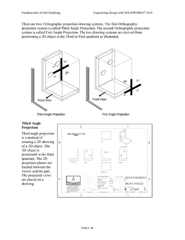
There are two Orthographic projection drawing systems. The first Orthographic
projection system is called Third Angle Projection. The second Orthographic projection
system is called First Angle Projection. The two drawing systems are derived from
positioning a 3D object in the Third or First quadrant as illustrated.
0
Front View Front View
Third Angle Projection First Angle Projection
Third Angle
Projection 2 1
Third angle projection THIRD ANGLE PROJECTION
VIEWS
is a method of
creating a 2D drawing B TO P B
of a 3D object. The ISOMETRIC
3D object is -(±)- -(±)-
' FRO NT •
positioned in the third -(±)-
•
quadrant. The 2D
projection planes are BOTTOM LEFT -~ RIGHT
' -,
I
located between the -·
' -,
I
I
'
viewer and the part. BOTTOM
The projected views
UNLESS OTHf;RWISE SPECIFIED: D&M ENGINEERING
UAMf >AH
are placed on a A ,ouv,,11(. u: Ol!AWII TITLE: A
OIMWJl()llj A•t 111 !IU; NU
(. " C¢Kt O
UA¢1,<)t1Al!
At10UlAI . MA¢11! U MI> ! tllGA,,t
IWO HACE OE¢1MAt :
drawing. 11iRU fl.AC E t>l¢"'Al ! MIO ,...,,,, RIGHT ANGLE
l!MUUI CfOMflh! O ,A
nort!O,U I ANO CONL'lllOi'HAl IO ltR/0,tl(.WG •tit' ----'
CO!AM(NIS:
IHf MJOtMAllOli COIITAMC, M lH5 rMIUl"l
OtAWll-lC II lllt SOLE U OtU!fY Of Pk:Jin Carbon Steel S~E DWG. NO . REV
<IH URI <OMf>AtlY WA.Mt HClt) A l ff .....
tltlOOUCll(>II NtAll Of M .... Wl'IOlt @--a A L-Partl A
WIHOUI Ill( WHUN PUt.l6$1(HI (I f IHtt ....SSY LUO OW
<ltlJUI <OMl> .... IIY iu.,.,t IIUt? 0
------ - -
, • <>~•~H>. AHUCA11011 • SHEET 1 O f 1
2 1
PAGE2 - 20